




Contents: Distributor ↓ Ignition coil ↓ Spark plugs ↓ Ignition switch ↓ Testing of radio interference…↓
Distributor
Attention. Before 1980, the engines used ignition distributors of the P-125 V type (Fig. 7-20). Since 1980, together with the 2107-1107010-20 carburetor, ignition distributors of the 30.3706-02 type (Fig. 7-21) began to be installed, which had a vacuum ignition advance regulator.
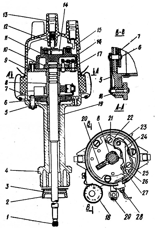
Fig. 7-20. Ignition distributor R-125V: 1 - roller; 2 - oil-deflecting clutch; 3 - spiral pin; 4 - body; 5 - traction; 6 - axis, 7 - movable breaker plate, 8 - breaker cam; 9 - driven plate; 10 - leading plate; 11 - rotor, 12 - central carbon electrode; 13 - central electrode terminal; 14 - resistor; 15 - side electrode; 16 - cover; 17 - weight; 18 - octane corrector eccentric; 19 - roller bushing; 20 - felt; 21, 25 - screws for fastening the stand with breaker contacts; 22 - rack with breaker contacts; 23 - lever spring; 24 - lever; 26 - groove for adjusting the position of the rack; 27 - breaker contacts; 28 - low voltage wire tip fastening nut; 29 - roller oiler
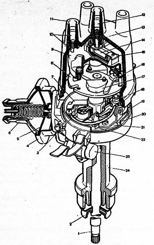
Fig. 7-21. Ignition distributor 30.3706-02: 1 - roller; 2 - oil-deflecting clutch; 3 - felt; 4 - vacuum regulator housing; 5 - membrane; 6 - vacuum regulator cover; 7 - vacuum regulator rod; 8 - centrifugal regulator support plate; 9 - ignition distributor rotor; 10 - side electrode with terminal; 11 - lid; 12 - central electrode with terminal; 13 - central electrode carbon; 14 - resistor; 15 - outer rotor contact; 16 - centrifugal regulator plate; 17 - weight; 18 - breaker cam; 19 - contact group: 20 - movable breaker plate; 21 - screw for fixing the contact group; 22 - groove; 23 - capacitor; 24 - ignition distributor housing
Before installing the ignition distributor on the stand, check the condition of the breaker contacts, whether the lever with the movable contact is jammed on the axis and the contact pressing force, which should be 4.9-5.88 N (500-600 gs). Check the breaker lever pad for wear; in case of wear, adjust the gap between the breaker contacts. If the lever is stuck on the axis or its spring is weakened, replace the contact group.
If the breaker contacts are dirty, burnt or eroded, clean them with a velvet file. Do not use sandpaper or other abrasive materials for this purpose.
After cleaning, wipe the contacts of the breaker with a chamois soaked in gasoline. Then pull the lever to evaporate the gasoline, and wipe the contacts again with a dry chamois. Instead of chamois, you can use any material that does not leave fibers.
The contacts must touch with their entire surface. If this does not happen, then by bending the rack bracket, adjust the position of the fixed contact. Do not bend the lever with the movable contact. Wipe the distributor cap from dirt and oil.
By slightly lifting the ignition distributor cover, check whether the breaker contacts are open.
Checking the work. Mount the distributor on a test bench for testing electrical devices and connect it to an electric motor whose rotation speed is adjustable.
Make connections to the ignition coil and to the battery; connect the four terminals of the cover on the stand with spark gaps, the gap between the electrodes of which is adjustable.
Set a 5 mm gap between the arrester electrodes, turn on the stand's electric motor and rotate the distributor shaft clockwise for several minutes at a frequency of 200 min⁻¹. Then increase the gap between the electrodes to 10 mm and watch for internal discharges in the distributor. Internal discharges are detected by sound or by weakening and interruption of sparking on the arrester of the test stand.
During operation, the ignition distributor should not produce significant noise at any shaft rotation speed.
Removal the automatic ignition advance characteristic. Install the distributor on the stand and make electrical connections according to the stand instructions. Turn on the stand electric motor and rotate the distributor shaft at a frequency of 150-200* min⁻¹. On the graduated disk, read off the value in degrees, according to which one of four sparks is obtained.
* 300-400 min⁻¹ for ignition distributor R-125V.
By increasing the rotation speed and taking readings at each increase of 200-300 min⁻¹, determine the number of degrees of advance relative to the initial value, depending on the rotation speed of the distributor shaft. Compare the resulting characteristic with the characteristic in Fig. 7-22.
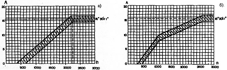
Fig. 7-22. Characteristics of the centrifugal regulator of the ignition distributor: a - ignition distributor R-125V; in - ignition distributor 30.3706-02; A - ignition timing angle, degrees; n - rotation frequency of the distributor shaft, min⁻¹
Checking the angle of the closed state of contacts. Turn on the stand's electric motor and increase the distributor shaft rotation speed to 1000 min⁻¹.
Using the illuminated areas of the scale, measure the value of the angle of the closed state of the contacts, which should be 55±3°.
After checking the angle of the closed state of the contacts, check the angles between the moments of opening of the contacts on the cylinders relative to the first (asynchronism), which should not differ from the nominal values by more than ±1°.
Removal the characteristics of the vacuum regulator. Connect the vacuum regulator of the ignition distributor with a hose to the vacuum pump of the stand. Turn on the electric motor of the stand and rotate the shaft of the ignition distributor at a frequency of 1000 min⁻¹. Using the graduated disk of the stand, set the conditional "zero" for the moment of sparking in any of the cylinders.
Smoothly increasing the vacuum, every 26.7 GPa (20 mm Hg) note the number of degrees of ignition advance relative to the initial value. Compare the resulting characteristic with the characteristic in Fig. 7-23.
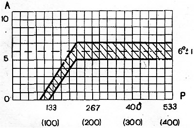
Fig. 7-23. Characteristics of the vacuum regulator of the ignition distributor 30.3706-02: A - ignition timing angle, degrees; P - vacuum, hPa (mm Hg.)
Adjust the vacuum regulator characteristic by selecting adjusting washers between the spring and the vacuum regulator plug.
Pay attention to the clarity of the return to the original position of the movable plate of the breaker after removing the vacuum.
Insulation resistance check. The insulation resistance between the various terminals and the ground is checked with a megohmmeter and should be at least 10 MOhm at (25±5)°C. The resistance between the low-voltage terminal of the breaker and the ground is measured with the breaker contacts open.
Checking the capacitor. The capacitor capacitance, measured in the frequency range between 50 and 1000 Hz, should be within 0.20-0.25 μF.
Ignition coil
To check the serviceability of the ignition coil, the following checks must be performed.
Ohmic resistance the primary winding resistance at 20°C should be 3.07-3.5 Ohm, and the secondary winding resistance 5400-9200 Ohm.
Isolation to ground. The ignition coil must be able to withstand an alternating current voltage of 1500 V and 50 Hz, applied for 1 min between one end of the primary winding and the housing, without any discharges.
The insulation resistance to ground must be greater than or equal to 50 MΩ.
Spark plugs
If misfires are noticed, especially in one or more cylinders, it is necessary to check the condition of the spark plugs.
Before testing, clean spark plugs with carbon deposits or dirt using a special installation with a sand jet and blow them with compressed air.
If the carbon deposit is light brown, it does not need to be removed, as it appears on a serviceable engine and does not interfere with the operation of the ignition system.
After cleaning, inspect the spark plugs and adjust the gap between the electrodes. If there are chips, cracks on the insulator or the weld on the side electrode is damaged, replace the spark plug.
Gap (0.5-0.6 mm) between the spark plug electrodes, check with a round wire feeler gauge from the tool kit supplied with the car. You cannot check the gap with a flat feeler gauge, as this does not take into account the notch on the side electrode that forms when the spark plug is in operation. Adjust the gap by bending only the side electrode of the spark plug. Do not bend the central electrode, as this can cause the ceramic insulator to break.
Leak test. Screw the spark plug into the corresponding socket on the stand, and then create a pressure of 2 MPa in the stand chamber (20 kgf/cm²).
Place a few drops of oil or kerosene on the candle from an oil can; if the seal is broken, air bubbles will escape, usually between the insulator and the metal body of the spark plug.
Electrical test. The gap between the spark plug electrodes is adjusted to 0.6 mm, screw it into the socket on the stand and tighten it with a torque wrench to 30.67-39 N·m (3.13-3.99 kgf·m); the tightness is ensured by the elastic gasket of the socket stud. Adjust the gap between the electrodes of the arrester to 12 mm, which corresponds to a voltage of 18 kV, and then use the pump to create a pressure of 0.6 MPa (6 kgf/cm²).
Place the high tension wire tip on the spark plug and press the switch button.
In this case, the following may be observed:
- 1. A full spark is visible in the eyepiece of the stand between the spark plug electrodes; in this case, the candle is considered excellent.
- 2. Sparking occurs between the electrodes of the spark gap: the pressure in the device should be reduced and the pressure at which sparking occurs between the spark plug electrodes should be checked. If at a pressure of 0.5 MPa (5 kgf/cm²), the spark plug is considered normal, and if at a pressure of 0.4 MPa (4 kgf/cm²) and below, it is defective.
Several sparks on the spark gap are allowed, if there is no spark formation on the spark plug and on the spark gap, it must be assumed that there are cracks on the spark plug insulator and that the discharge occurs inside between the "mass" and the electrodes. Such a spark plug is considered defective.
Ignition switch
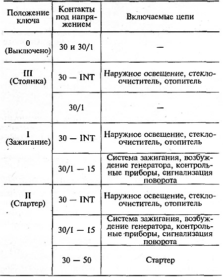
The ignition switch is checked for operation of the anti-theft device and correct contact closure in different key positions (see table 7-5). Voltage from the battery and generator is supplied to contacts "30" and "30/1". The free plug "INT" is used to connect the radio receiver.
Table 7-5. Circuits switched on at different key positions
The anti-theft device locking rod must extend when the key is set to the "PARK" position and removed from the lock. The rod must retract after turning the key from the "PARK" position to the "OFF" position.
When installing the contact part into the switch housing, it must be positioned so that the plugs "15" and "30" are on the side of the locking rod (see fig. 7-24), in this case, the wide protrusion of the contact part will enter the wide groove of the switch housing.
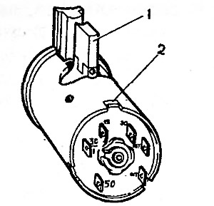
Fig. 7-24. View of the contact part of the ignition switch: 1 - locking rod; 2 - wide protrusion of the contact part
Testing of radio interference suppression elements
The elements for suppressing radio interference include high-voltage wires with a distributed resistance of 2000±200 Ohm/m and a noise-suppressing resistor in the ignition distributor rotor with a resistance of 5000-6000 Ohm. The operability of these elements is checked with an ohmmeter.
View the original on the internet resource (VAZBOOK)