




Contents: Checking functionality ↓ Full braking test ↓ Idle speed test ↓ Checking the traction relay ↓ Mechanical data check ↓
To ensure the efficiency of the starter, it is necessary to test its electrical and mechanical characteristics on a bench. The electrical circuit for testing the starter on a bench is shown in Fig. 162. The connecting wires to the current source, ammeter and contact bolt of the starter traction relay must have a cross-section of at least 16 mm³. The starter must be powered from a fully charged battery, the temperature during testing must be (25±5)°C, and the brushes must be well ground to the commutator.
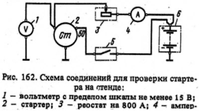
Checking functionality
By closing switch 5, when voltage is applied (...the text is missing...) starter with different braking conditions. For example, with braking torques; 0,2—0,24; 0,55—0,66; 0.9-1.08 and 1.15-1.25 kgf·m. The duration4 of each starter activation should be no more than 5 s, and the intervals between activations should be no less than 5 s.
If the starter does not rotate the stand's toothed ring or its operation is accompanied by abnormal noise, then disassemble the starter and check its parts.
Full braking test
The toothed ring of the stand is braked, the starter is turned on and the current, voltage and braking torque are measured, which should be no more than 500 A, no more than 6.5 V and no less than 1.4 kgf·m, respectively. The duration of the starter activation should be no more than 5 s.
If the braking torque is lower and the current is higher than the specified values, the reason may be an interturn short circuit in the stator and anchor windings or a short circuit of the windings to ground. When the braking torque and consumed current are lower than the above values, the reason may be oxidation and contamination of the collector, severe wear of the brushes or a decrease in the elasticity of their springs, hanging in the brush holders, loosening of the stator winding terminals, oxidation or burning of the contact bolts of the traction relay.
When the pinion is fully braked, the starter anchor should not turn. If this happens, the freewheel clutch is faulty. To eliminate the fault, disassemble the starter and replace the damaged parts.
Idle speed test
The toothed ring of the stand is removed from engagement with the starter gear. The starter is turned on and the consumed current and the rotation frequency of the anchor are measured, which should be no more than 35 A, respectively (60 A for starter 35.3708) and 5000+500-800 rpm at a voltage of 11.5–12 V at the starter terminals.
If the current strength and the rotation speed of the armature shaft differ from the specified values, then the reasons may be the same as in the previous test.
Checking the traction relay
Installed between the limiting ring 1 (see fig. 161) and a 12.8 mm thick gasket with a gear and turn on the relay. For a single-winding relay, the consumed current is checked, which should be no more than 23 A. For a two-winding relay, the relay turn-on voltage is checked, which should be no more than 9 V at an ambient temperature of (20±5)°C.
Mechanical data check
The spring pressure on the brushes is checked with a dynamometer; for new brushes, it should be (1±0.1) kgf. If the brushes are worn to a height of 12 mm, they are replaced after being ground to the collector.
The axial play of the anchor shaft should be 0.07-0.70 mm. If it is not within this limit, then disassemble the starter and select the thickness and number of adjusting washers 20 (see fig. 163).
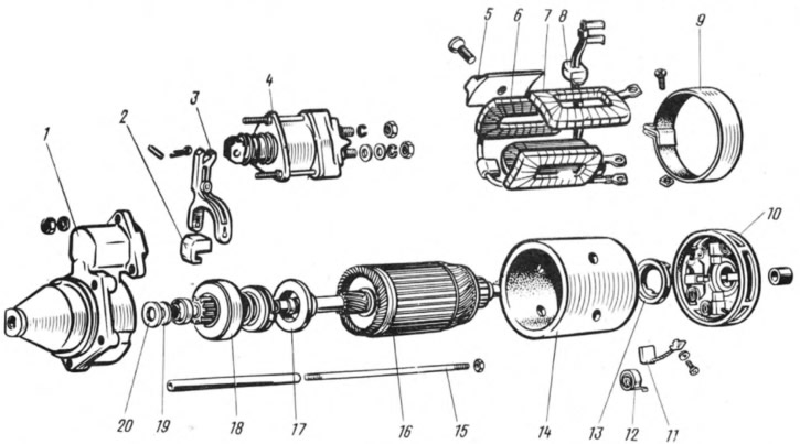
Fig. 163. Starter parts:
1 - starter cover on the drive side; 2 - rubber plug; 3 - drive lever; 4 - traction relay; 5 - stator pole; 6 - series stator winding; 7 - stator shunt winding; 8 - rubber plug; 9 - protective tape; 10 - cover from the collector side; 11 - brush; 12 - brush spring; 13 - brake disc cover; 14 - body; 15 tie rod; 16 - anchor; 17 - gear travel limiter; 18 - overrunning clutch with drive gear; 19 - thrust washer; 20 - adjusting washer.
The starter drive must move freely along the splined shaft without noticeable jamming and return from the working position to the initial position under the action of the return spring of the relay anchor. When the drive gear turns in the direction of rotation of the anchor, the latter should not rotate. The gear must rotate relative to the anchor shaft under the action of a torque of no more than 2.8 kgf cm.