
English Русский
Български
Беларускі
Український
Српски
Hrvatski
Română
Polski
Slovenský
Magyar
| Articles | Contacts | Sitemap |   
Repair and maintenance Lada Repair and maintenance Mazda Repair and maintenance Mitsubishi Repair and maintenance Toyota Repair and maintenance Land Rover Repair and maintenance Hyundai Repair and maintenance Nissan
VAZbook.ru


Main     1111   2101   2105   2106   2107   2109   2110   2115   2121  
VAZ-2101 (1970-1983) VAZ-21011 (1974-1983)
  • Main
  • «Zhiguli»
  • VAZ-2101
  • Electrical equipment
  • Engine electrics
  • The structure and operation of the starter

The structure and operation of the starter (VAZ-2101)

            0

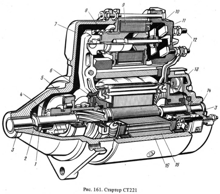
The ST221 starter (Fig. 161) is a four-pole, four-brush DC electric motor with mixed excitation, with electromagnetic engagement of the drive gear and remote control.

The ST221 starter (Fig. 161) is a four-pole, four-brush DC electric motor with mixed excitation,…


The covers and the starter housing are pulled together with studs that are screwed into the cover 7 and insulated with plastic tubes. Four poles 15 are installed in the housing 16 - two with series windings included in the circuit in series with the anchor, and two with shunt windings (coils) included in parallel.

The anchor 14 of the starter consists of a shaft, a core with a winding and a collector. The core is assembled from electrical steel plates pressed onto the middle part of the shaft and has semi-closed grooves in which the anchor winding is laid. The collector consists of a plastic base reinforced with two steel rings, on which copper plates insulated from each other are installed - the collector lamellas.

The anchor shaft rotates in two porous metal-ceramic bushings 3, pressed into the starter covers and impregnated with oil. The axial free play of the anchor shaft is adjusted by selecting washers 2 and should be within 0.07-0.7 mm.


The starter drive is mounted on the front end of the anchor shaft, consisting of a free-running roller clutch 5 and gear 1. Plastic disks are mounted on the clutch hub — a centering disk with a steel leash ring 6 and a limiting disk. They are pressed against the locking ring on the hub by a spring. The hub has internal screw splines on one side and can, by turning, move along the screw splines of the anchor shaft. On the other side, an oil-impregnated metal-ceramic insert is pressed into the hub, sliding along the smooth part of the shaft. The gear has a brass bushing with graphite inclusions.

In the cover 13, 4 brush holders with copper-graphite brushes are fixed with rivets. Two brush holders are insulated from the cover with plastic plates. These are the brush holders of the positive brushes. The terminals of the series stator coils are connected to them. The other two brush holders are attached directly to the cover and, therefore, are connected to the "mass". The terminal of the shunt coils is connected to one of them. The brushes are pressed to the collector with spiral springs.

The starter traction relay is attached to cover 7, consisting of an anchor 8, a winding 9, a contact plate 10 and a cover 11 with contact bolts 12. The traction relay switches on the starter and engages gear 4 with the flywheel ring gear.

The dimensions of the relay and drive components are selected so that the relay contacts close when the pinion has only partially engaged with the flywheel ring. The starter anchor begins to rotate, the clutch hub is unscrewed from the anchor shaft splines and the pinion is sent to the stop in ring 1, fully engaging with the flywheel,


Since 1983, the ST221 starters have used a traction relay with two windings - a pull-in winding and a holding winding. When the starter is turned on, both windings operate first. After the contacts of the traction relay are closed, the pull-in winding is disconnected, and the relay armature is held in the on position by one holding winding.

Since 1986, cars have been equipped with a 25.37.08 starter, which has an end collector, as well as three series stator windings and one shunt winding. The end collector is made in the form of a plastic disk with copper plates poured into it. Otherwise, the design of the 35.3708 starter is the same as that of the ST221 starter. The traction relay is two-winding.

Technical characteristics of the starter:

Nominal power, kW — 1.3

Current consumption, A, no more than:
  • at maximum power - 260
  • in a inhibited state - 500
  • idling speed: ST221-35


This article is available at russian, bulgarian, belarusian, ukrainian, serbian, croatian, romanian, polish, slovak, hungarian
The text was reviewed by the specialist: Grigory Vologodtsev

Share with friends:

Previous articles
VAZ-2101: Engine electrics
Next articles

Battery charge indicator lamp relay
Voltage Regulator Repair
Troubleshooting a Voltage Regulator
Checking and adjusting the voltage regulator
The device and operation of the voltage regulator
Possible faults starter
Checking the starter on the stand
Disassembling and assembling the starter
Checking the technical condition and repairing the starter
The structure and operation of the ignition system

More articles from other manuals on VAZ cars:
➠ The structure and operation of the starter VAZ-1111 (1988-1996)
➠ The structure and operation of the starter VAZ-2109 (1984-1997)
➠ The structure and operation of shock absorbers VAZ-2105 (1979-2010)
➠ The structure (layout) of VAZ-2106 and VAZ-2103 cars VAZ-2106 (1976-2006)
➠ General recommendations for vehicle operation VAZ-2107 (1982-2012)
Link in different formats to this page


Visitor comments

No comments yet


How much will 17 + 22 ?


VAZ-2101 (1970-1983) 
  • General information
  • Vehicle description
  • Vehicle device
  • Vehicle operation
  • Maintenance
  • Main malfunctions
  • Applications
  • Power unit
  • Engine repair
  • Cooling and lubrication system
  • Supply system
  • Transmission
  • Clutch
  • Transmission
  • Cardan gear
  • Rear axle
  • Chassis
  • Front suspension
  • Rear suspension
  • Steering
  • Brake system
  • Body
  • Exterior
  • Interior
  • Electrical equipment
  • Engine electrics
  • Equipment and devices


VAZ-21011 (1974-1983) 
  • General information
  • Specifications
  • Operation and maintenance
  • Power unit
  • Engine repair
  • Cooling system
  • Lubrication system
  • Power and exhaust system
  • Ignition system
  • Engine electrics
  • Transmission
  • Clutch
  • Car gearbox
  • Cardan gear
  • Rear axle
  • Chassis
  • Car suspension
  • Steering
  • Brake system
  • Body
  • Exterior
  • Interior
  • Doors and locks
  • Electrical equipment
  • Equipment and devices
  • Lighting and signaling


VAZbook.ru © 2017 · Mobile version · Contact with administration · Sitemap: EN BG BY UA RS HR RO PL SK HU · Site search · News and articles VAZ-1111 · VAZ-11113 · VAZ-2101 · VAZ-21011 · VAZ-2104 · VAZ-2105 · VAZ-21051 · VAZ-2106 · VAZ-21061 · VAZ-2107 · VAZ-21099 · VAZ-2109 · VAZ-2108 · VAZ-2110 · VAZ-2112 · VAZ-2114 · VAZ-2115 · VAZ-2121 · VAZ-21213 · VAZ-21214 ·
The site stores technical data using cookies to improve the service.