
Differential Assembly
Install the axle gears with support washers and satellites in the differential box. The satellites and gears of the semi-axes are turned so as to align the axis of rotation of the satellites with the axis of rotation in the box, then the axis of the satellites is inserted.
Check the axial play of each gear of the axle shaft. It should be no more than 0.10 mm. If the clearance is increased, which is a sign of excessive wear on the gears, replace the support washers of a suitable thickness. If the specified clearance cannot be obtained even when the washers of the greatest thickness are installed, the gears are replaced with new ones.
The driven gear is installed and the inner rings of the bearings are pressed onto the differential box with the mandrel A.70152. The mandrel is made of a pipe with an outer diameter of 43 mm and an inner diameter of 35.2 mm.
Installing and adjusting the drive gear
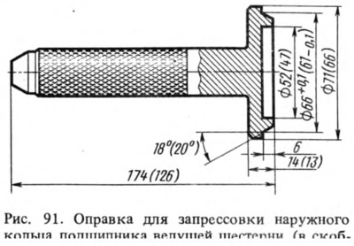
Having fixed the gearbox crankcase on the stand, the outer rings of the front and rear bearings of the drive gear are pressed into the crankcase sockets, using mandrels for this. A.70185 for the front bearing and A.70171 for the rear (pic. 91).
On mandrel А.70184 (7 - fig. 92), imitating the drive gear, install the inner ring of the rear bearing and insert the mandrel into the neck of the gearbox housing. Install the inner ring of the front bearing, the drive gear flange and, turning the mandrel to properly install the bearings, tighten the nut (tightening torque 0.8—1 kgf·m).
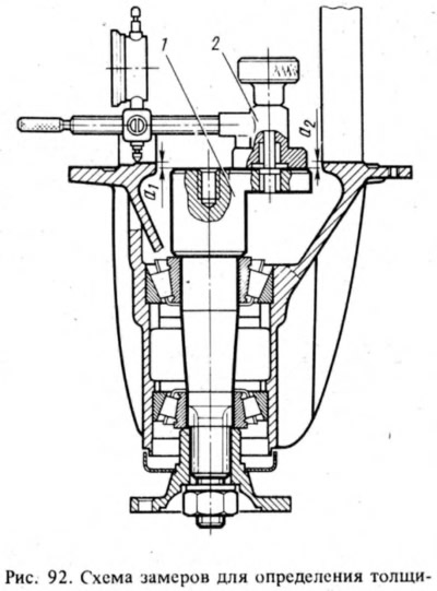
Fix fixture (A.95690) on the end of mandrel 1 and adjust the indicator having a division of 0.01 mm by zero by setting its leg on the same end of mandrel A.70184. Then the indicator is moved so that its leg rests on the seating surface of the bearing of the differential box. By turning the mandrel with the indicator left and right, set it to a position in which the indicator needle marks the minimum value of a1, and write it down. Then repeat this operation on the seating surface of the second bearing and determine the value of a2.
After that, the thickness S of the adjusting ring of the drive gear is determined, which is the algebraic difference between the values a and b, i.e. where a = (A1 + a2) /2; b - deviation of the drive gear from the nominal position, mm. The deviation value is marked on the drive gear in hundredths of a millimeter with a sign "+" or "—".
When determining the thickness of the adjusting ring, the sign of b and its unit should be taken into account.
Example. Assume that the value of a set using the indicator is 2.91 mm (but always positive), and on the drive gear after the serial number there is a number minus 14. To get b in millimeters, multiply this number by 0.01, i.e. b \u003d -14 0.01 mm \u003d -0.14 mm.
Determine the thickness of the adjusting ring for the drive gear in millimeters:
S = a — b = 2,91 — (-0,14) = 2.91 + 0.14 = 3.05 mm.
In this case, it is necessary to install an adjusting ring with a thickness of 3.05 mm.
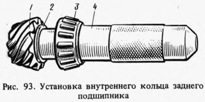
Put on the drive gear 1 (pic. 93) adjusting ring 2 of the required thickness and pressed with a mandrel 4 (A.70152) the inner ring 3 of the rear bearing, removed from the mandrel A.70184. Put on a spacer sleeve.
When overhauling the gearbox, a new spacer must be installed if the gearbox housing, final drive pinion, or pinion bearings have been replaced. If the specified parts remain the same, the spacer sleeve can be reused.
Insert the drive gear into the gearbox housing and install the front bearing inner ring, mud deflector, oil seal, drive gear flange and washer on it. Screw a nut onto the end of the drive gear and, locking the flange of the drive gear, tighten it (tightening torque 12-26 kgf·m).
Tightening the pinion bearings
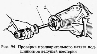
To limit the axial displacements of the drive gear under operating loads, it is very important to create a preload in its bearings within the specified limits. The preload is controlled by a dynamometer 02.7812.9501, which allows you to measure the moment of resistance to turning the gear. This torque determines the degree of tightening of the bearings. It should be 16-20 kgf cm for new bearings and 4-6 kgf cm for bearings after a run of 30 km or more. The flange nut should be tightened to a torque of 12-26 kgf·m, periodically checking the moment of resistance of the bearings to turning the drive gear.
To check the moment of resistance put on a dynamometer 1 (pic. 94) on the adapter sleeve 2 and the handle make several turns clockwise. While turning the drive gear, the movable dynamometer indicator should not go beyond the limiter and should show at least 16 kgf cm. If the moment of resistance to rotation is less than 16 kgf cm (4 kgf cm for bearings after 30 km run), it is necessary to tighten the drive gear flange nut (without exceeding the specified tightening torque) and check again the moment of resistance to turning the drive gear. If the moment of resistance to rotation turned out to be more than 20 kgf cm (6 kgf cm for run-in bearings), this indicates an excessive bearing preload. In this case, it is necessary to replace the spacer sleeve, as it has been deformed from excessive load to a size that does not allow for correct adjustment. After replacing the spacer sleeve, repeat the assembly with the appropriate adjustments and checks.
Installing the differential box
Install the pre-assembled box together with the differential into the gearbox housing, tighten the adjusting nuts 1 (pic. 95), so that they are in contact with the bearing rings and the bearing caps. Tighten the mounting bolts.
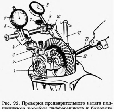
The preload of the bearings of the differential box and the adjustment of the lateral clearance in the meshing of the final drive gears are carried out simultaneously using tool A.95688/R and key 12 (A.55085). To do this, the fixture is fixed on the gearbox housing with screws 11 and 3, screwing them into the holes for the bolts for fastening the locking plates of the adjusting nuts. The bracket 4 of the indicator is shifted along the guide of the device until the lever 2 touches the outer side surface of the cover and tighten the screw 5. Loosen the screws 7 and 9 and install the bracket 10 so that the indicator leg 8 rests on the side surface of the tooth of the driven gear at the edge of the tooth. Then tighten screws 7 and 9.
Turning the adjusting nuts, pre-adjust the lateral clearance between the teeth of the gears within 0.08-0.13 mm according to indicator 8 while rocking the driven gear 13. In this case, the bearings should not have a preload. The adjusting nuts must only be in contact with the bearings. Otherwise, the correct preload measurement will be impaired.
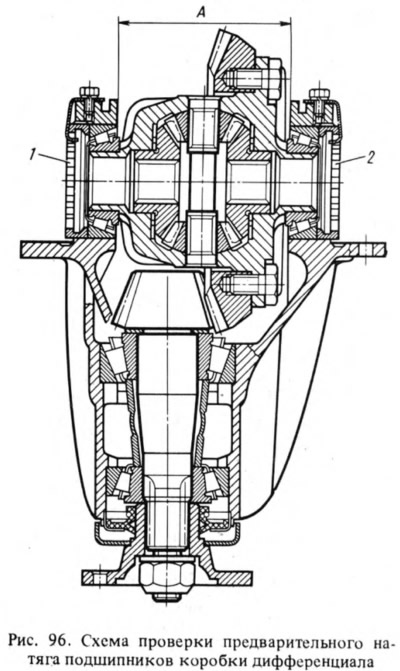
Consistently and evenly tighten the two adjusting nuts 1 and 2 (pic. 96) bearings. In this case, the differential bearing caps diverge and the distance increases. This discrepancy is indicated by indicator 6 (see fig. 95), on the leg of which the lever acts 2. The nuts for adjusting the bearings of the differential box are tightened to increase the distance A (see fig. 96) by 0.14-0.18 mm.
Having set the exact preload of the bearings of the differential box, they finally check the side clearance in the meshing of the final drive gears, which should not change. If the gap in the meshing of the gears is more than 0.08-0.13 mm, then the driven gear is brought closer to the leading one. If the gap is smaller, then push back. To maintain the set bearing preload, the driven gear is moved by tightening one of the bearing adjusting nuts and loosening the other by the same angle.
To accurately perform this operation, you must follow the indicator 6 (see fig. 95), which shows the previously set bearing preload. After tightening one of the nuts, the indicator reading will change as distance A increases (see fig. 96) and bearing preload. Therefore, the other nut is loosened until the indicator needle returns to its original position.
After moving the driven gear, but the indicator 8 (see fig. 95) check side clearance. If the gap is not correct, repeat the adjustment.
After adjustment, remove tool A.95688/R, install the locking plates of the adjusting nuts and secure them with bolts and spring washers. Spare parts are supplied with locking plates in two types: with one and two tabs. One or the other plate is installed depending on the position of the nut slot.
Checking the contact of the working surface of the gear teeth
To check the quality of engagement:
- install the adjusted gearbox on the stand and lubricate the working surfaces of the teeth of the driven gear with a thin layer of lead oxide;
- start the stand and the levers of the stand slow down the rotation of the semi-axes so that under load on the surfaces of the teeth of the driven gear there are traces of contact with the teeth of the drive gear;
- change the direction of rotation and, braking, get contact marks on the other side of the teeth of the driven gear, which corresponds to the movement of the car back.
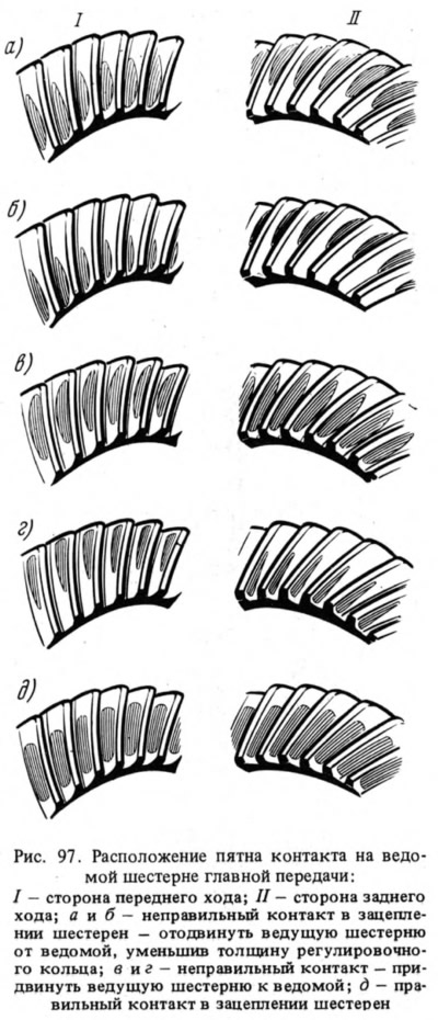
Engagement is considered normal if on both sides of the teeth of the driven gear the contact patch is evenly located closer to the narrow end of the tooth, occupying 2/3 of its length and not reaching the top and base of the tooth, as shown in Fig. 97, d.
To adjust the correct position of the drive gear with the replacement of the ring, disassembly of the assembly is necessary. When assembling, it is necessary to repeat all the operations for preloading the drive gear bearings, checking the moment of resistance to rotation, preloading the bearings of the differential box and adjusting the backlash of the final drive gears.