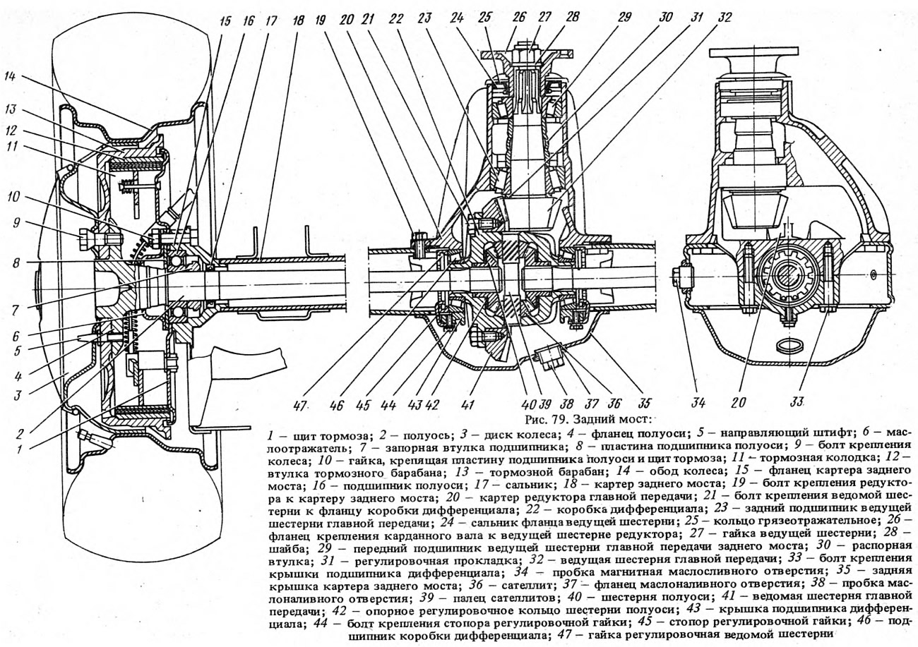
The reduction gear, which contains the main gear and differential, is attached to the housing (beam) 18 (Fig. 79) of the rear axle. The leading 32 and driven 41 gears of the main gear are paired in terms of contact and noise, so if one of them is damaged, both are replaced. Between the inner rings of the bearings 23 and 29 of the leading gear, there is a spacer sleeve 30, which, deforming when the nut of the leading gear is tightened, provides a preliminary tension in the bearings.
Open large image in new tab »
Fig. 79. Rear axle:
1 - brake shield; 2 - half shaft; 3 - wheel disk; 4 - axle shaft flange; 5 - guide pin; 6 - oil deflector; 7 - bearing locking sleeve; 8 - axle shaft bearing plate; 9 - wheel mounting bolt; 10 - nut securing the axle bearing plate and brake shield; 11 - brake shoe; 12 - brake drum bushing; 13 - brake drum; 14 - wheel rim; 15 - rear axle housing flange; 16 - axle shaft bearing; 77 - oil seal; 18 - rear axle housing; 19 - bolt for fastening the gearbox to the rear axle housing; 20 - main gear reducer housing; 27 - bolt for fastening the driven gear to the differential box flange; 22 - differential box; 23 - rear bearing of the main gear pinion; 24 - drive gear flange seal; 25 - mudguard ring; 26 - flange for fastening the cardan shaft to the drive gear of the gearbox; 27 - drive gear nut; 28 - washer; 29 - front bearing of the main gear pinion of the rear axle; 30 - spacer sleeve; 31 - adjusting gasket; 32 - main gear drive pinion; 33 - differential bearing cover mounting bolt; 34 - magnetic oil drain plug; 35 - rear axle housing rear cover; 36 - satellite; 37 - oil filler flange; 38 - oil filler plug; 39 - satellite finger; 40 - axle gear; 41 - driven gear of the main transmission; 42 - support adjusting ring of the axle gear; 43 - differential bearing cover; 44 - adjusting nut stopper mounting bolt; 45 - adjusting nut stopper; 46 - differential box bearing; 47 - driven gear adjusting nut.
1 - brake shield; 2 - half shaft; 3 - wheel disk; 4 - axle shaft flange; 5 - guide pin; 6 - oil deflector; 7 - bearing locking sleeve; 8 - axle shaft bearing plate; 9 - wheel mounting bolt; 10 - nut securing the axle bearing plate and brake shield; 11 - brake shoe; 12 - brake drum bushing; 13 - brake drum; 14 - wheel rim; 15 - rear axle housing flange; 16 - axle shaft bearing; 77 - oil seal; 18 - rear axle housing; 19 - bolt for fastening the gearbox to the rear axle housing; 20 - main gear reducer housing; 27 - bolt for fastening the driven gear to the differential box flange; 22 - differential box; 23 - rear bearing of the main gear pinion; 24 - drive gear flange seal; 25 - mudguard ring; 26 - flange for fastening the cardan shaft to the drive gear of the gearbox; 27 - drive gear nut; 28 - washer; 29 - front bearing of the main gear pinion of the rear axle; 30 - spacer sleeve; 31 - adjusting gasket; 32 - main gear drive pinion; 33 - differential bearing cover mounting bolt; 34 - magnetic oil drain plug; 35 - rear axle housing rear cover; 36 - satellite; 37 - oil filler flange; 38 - oil filler plug; 39 - satellite finger; 40 - axle gear; 41 - driven gear of the main transmission; 42 - support adjusting ring of the axle gear; 43 - differential bearing cover; 44 - adjusting nut stopper mounting bolt; 45 - adjusting nut stopper; 46 - differential box bearing; 47 - driven gear adjusting nut.
An adjusting ring 31 is installed between the end of the drive gear and the inner bearing, determining the correct position of the drive gear relative to the driven gear.
The driven gear of the main transmission is attached to the flange of the differential box 22, which rotates on two bearings 46. The preliminary tension in these bearings, as well as the gap between the teeth of the driving and driven gears, is adjusted by nuts 47, screwed into the detachable bearing beds. The half-axle gears 40 are installed in the cylindrical seats of the differential box and rest on the box through support washers 42. By selecting the washers by thickness, a lateral gap of 0.0-0.1 mm is set between the teeth of the satellites and half-axle gears.
The axle shaft 2 enters the splined hole of the axle gear with its inner end, and rests on the ball bearing 16 with its outer end, which is secured to the axle shaft by a locking ring 7. The axle shaft bearing is sealed in the axle beam socket on the inner side by a self-tightening seal 17, and on the outer side by a rubber ring. The bearing is secured in the beam socket by a plate 8, which, together with the oil deflector 6 and the brake shield 1, is fastened with four bolts to the flange 15 of the beam.
The original is on the portal VAZbook
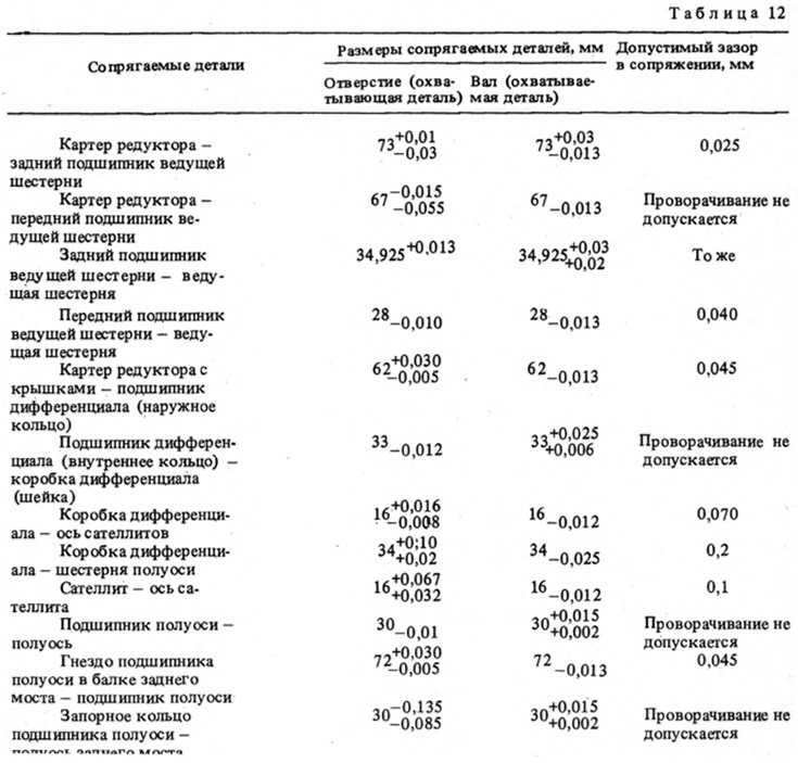
The dimensions of the main mating parts and the limits of permissible wear during operation are given in Table 12.