




Open large image in new tab »
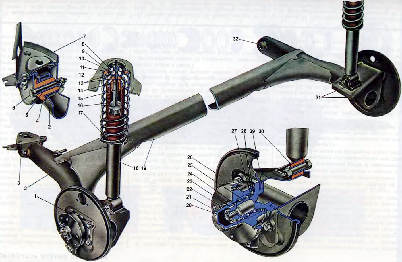
Figure 24. Rear suspension: 1. Rear wheel hub; 2. Rear suspension arm; 3. Suspension arm mounting bracket; 4. Rubber bushing of the lever hinge; 5. Expansion sleeve of the lever joint; 6. Rear suspension arm mounting bolt; 7. Body bracket; 8. Shock absorber rod mounting support washer; 9. Upper suspension spring support; 10. Spacer sleeve. 11. Suspension spring insulating gasket; 12. Rear suspension spring; 13. Shock absorber rod mounting pads; 14. Compression stroke buffer; 15. Shock absorber rod; 16. Shock absorber protective cover; 17. Lower support cup of suspension spring; 18. Shock absorber; 19. Lever connector; 20. Hub axle; 21. Cap; 22. Wheel hub fastening nut; 23. Sealing ring; 24. Bearing washer; 25. Hub bearing; 26. Brake shield; 27. Retaining ring; 28. Mud deflector; 29. Suspension arm flange; 30. Shock absorber bushing; 31. Lever bracket with eye for mounting shock absorber; 32. Rubber-metal hinge of the suspension arm.
The car is equipped with a torsion-link suspension of the rear wheels. The guide device of the suspension is two longitudinal levers 2, connected to each other by an elastic connector 19. Since the connector is significantly shifted forward from the wheel axis, then in its kinematic properties the suspension corresponds to an independent suspension on longitudinal levers. The independence of the movement of each wheel is ensured by twisting the amplifier, which has a U-shaped section, which has high bending rigidity and low torsional rigidity.
The longitudinal levers 2 are made of a pipe. They are welded to the connector 19 through the lever amplifiers and form, together with the connector, a single beam pivotally suspended through brackets 3 to the body. Each suspension lever has a bushing at the front, into which a rubber-metal hinge 32 is pressed, consisting of a rubber 4 and a metal 5 bushing. A bolt 6 passes through the spacer sleeve 5, connecting the suspension lever with a stamped bracket 3, which is fastened to the bracket 7 of the body with welded bolts with nuts and washers. A self-locking nut is screwed onto the lever fastening bolt. Brackets 31 with lugs for fastening shock absorbers and flanges 29 for fastening with bolts the axle 20 of the rear wheel hub and the shield of the rear wheel brake mechanism are welded to the rear part of the levers.
The elastic elements of the suspension consist of a spring 12 and a buffer 14 of the compression stroke. The spring is made of round spring steel. It is installed on the shock absorber 18 and rests with its lower part on the cup 17, and with its upper part on the support 9, welded to the inner arch of the body. The lower support cup of the spring is welded to the shock absorber. An insulating rubber gasket 11 is installed between the spring and the upper support.
The rear suspension springs, like the front ones, are divided into two classes by length under the control load - A and B. Class A springs are marked with yellow paint on the outer side of the middle coils, class B - green.
The buffer 14 of the compression stroke is made of polyurethane. It is installed on the shock absorber rod inside the suspension spring. From above, the buffer rests against the cover of the protective casing 16, and when switched on, against the buffer support, which is pressed onto the upper part of the shock absorber reservoir. On the outer surface of the buffer, there are annular grooves that determine the place of its deformation. The protective casing 16 protects the rod 15 of the shock absorber and the buffer 14 of the compression stroke from contamination and mechanical damage. The casing is made of rubber, has a corrugated shape to change the length during suspension travel. In the upper part of the casing, an annular groove is made from the inside, into which the flanged part of the steel cover goes. The lower part of the casing, due to its elasticity, is pressed against the support cup of the suspension spring.
The axle 20 of the rear wheel is attached to the flange of the suspension arm with four bolts. The shield 26 of the rear wheel brake mechanism is attached simultaneously with the axle with the same bolts. The hub 1 of the rear wheel rotates on the axle on a double-row ball bearing. The hub is attached to the axle with a nut 22 with a thrust washer 24. The nut is fixed on the axle by pressing its belt into the groove of the axle. Bearing 25 in the hub is fixed with a locking ring 27. The bearing is of a closed type, with embedded "eternal" grease. On the inside, the hub is sealed with two mud-deflecting rings 28, one of which is welded to the wheel hub, the other to the flange of the axle. A labyrinth seal is formed between them. On the outside, the hub cavity is closed with a cap 21. A sealing ring 23 is installed between the hub and the cap. The wheel hub bearing is not lubricated or adjusted during vehicle operation. The wheel disk is attached to the wheel hub with four bolts.
Shock absorber 18 of the rear suspension is a hydraulic telescopic double-acting shock absorber. The shock absorber is attached to bracket 31 of the lower suspension arm with a bolt and a self-locking nut by its lower eye. The upper shock absorber mount is a pin mount: the rod is attached to the upper support 9 of the spring through two rubber cushions 13 and a support washer 8. A spacer sleeve 10 is installed between the washer and the cover of the protective casing.
[The original can be found on the website VAZbook.ru]