




2. After bending the locking plates, unscrew the bolts that secure the caliper to the bracket. Move the caliper aside and secure it so that it does not hang on the hoses. Remove the shock absorbers with brackets.
3. Disconnect the ends of the stabilizer bar links from the lower control arms.
4. Using puller 67.7801.9513, press the pins out of the lever holes and move the steering rods to the side.
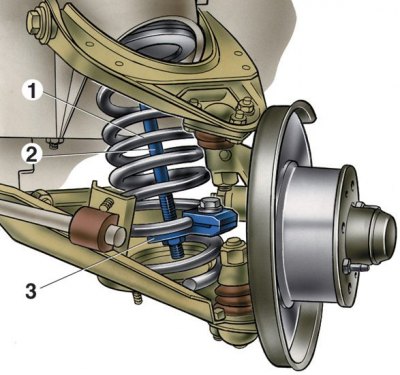
5. Insert screw 2, tool 67.7828.9504, into the hole of the upper support of the suspension spring, then put support plate 3 on the spring coil 1 and on screw 2 from below and secure it to the spring with a clamp. Screw a nut onto the screw from below so that the nut lock fits into the socket of plate 3. Turn screw 2 with a wrench to compress the suspension spring until the suspension arms are completely unloaded.
6. Remove the upper control arm axle and disconnect it from the body. Disconnect the lower control arm axle from the crossmember and remove the suspension unit from the vehicle.
7. Remove the spring, smoothly unload it, remove the device and repeat the operations for the other suspension unit.
Attention! When removing suspension units, it is necessary to mark the number and location of washers between the lower arm axis and the cross member, as well as the adjusting plates between the cross member and the body side members, so that when installing the units, these washers and plates are put back in their original place.
8. Remove the engine splash guard and stabilizer bar.
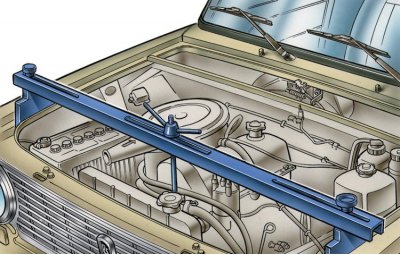
9. Supporting the engine with a crossmember A.70526 or a hoist, remove the crossmember.
10. Install the suspension units and parts in the reverse order of removal. Install the same group of springs on the front and rear suspensions (group A is marked with yellow paint, and group B springs are marked with green paint). In exceptional cases, it is permissible to install group A springs on the front suspension and group B springs on the rear suspension. If group B springs are installed on the front suspension, then install springs of the same group on the rear suspension.
11. To prevent incorrect distribution of forces in rubber-metal hinges, tightening of nuts and lever axles must be done in the following order:
- place the car on a level surface and position the wheels parallel to the car's axis;
- load the car with a load of 320 kgf (four people 40 kg in the trunk);
- under these conditions, using a torque wrench, tighten the nuts securing the axles of the upper and then the lower arms and the nuts securing the axle of the lower arm to the crossmember.
12. Check and adjust the front wheel alignment angles.