

Open large image in new tab »
Pic. 22: 1. Bracket for attaching the stabilizer bar to the side member of the body. 2. Stabilizer bar cushion. 3. Anti-roll bar. 4. Body spar. 5. The axis of the lower arm. 6. Lower suspension arm. 7. Bolts for fastening the axle of the lower arm to the suspension cross member. 8. Clip mounting the stabilizer bar. 9. Suspension spring. 10. Shock absorber. 11. A bolt of fastening of an arm of the shock-absorber to the bottom lever. 12. Shock absorber mounting bolt. 13. An arm of fastening of the shock-absorber to the bottom lever. 14. Lower support spring cup. 15. Holder of the insert of the lower support. 16. Protective cover of the upper ball joint. 17. Front wheel hub. 18. Roller tapered bearings of the front wheel hub. 19. Protective cover of the ball pin. 20. Lower support cage insert. 21. Bearing of the lower support. 22. Ball pin of the lower support. 23. Hub cap. 24. Adjusting nut. 25. Washer. 26. Steering knuckle pin. 27. Hub seal. 28. Brake disc. 29. Swivel fist. 30. Front wheel swivel limiter. 31. Ball pin of the upper support. 32. Upper support bearing. 33. Upper suspension arm. 34. Ball joint. 35. Buffer compression stroke. 36. Arm of the buffer of a course of compression. 37. Support glass shock absorber. 38. Cushion for fastening the shock absorber rod. 39. Washer of a pillow of a shock-absorber rod. 40. Suspension spring seal. 41. The upper support cup of the suspension spring. 42. The axis of the upper suspension arm. 43. Adjusting washers. 44. Distance washer. 45. Bracket for fastening the cross member to the side member of the body. 46. Front suspension cross member. 47. Inner bushing of the hinge. 48. Outer bushing of the hinge. 49. Rubber bushing hinge. 50. Thrust washer hinge. I - Camber angles (β) and transverse inclination of the axis of rotation (γ). II - Pitch angle (α). III - Toe-in (L2-L1).
The connecting link between the wheels and the body are the front and rear suspensions of the car. Through them, the forces acting on the wheels are transmitted to the body. The elements included in the suspension soften the load, reduce body vibrations, provide good stability and smoothness of the car. These elements include a guide device, elastic elements, shock absorbers and an anti-roll bar.
Suspension guide determines the nature of the movement of the wheel relative to the road and the body and transmits forces and moments from the wheel to the body. This device includes the upper 33 and lower 6 suspension arms and the knuckle 29 pivotally connected to them.
The upper arm is connected by axle 42 to the front end of the body using rubber-metal hinges. The axis, made in the form of a bolt with a hexagonal head, passes through the eyes of the lever 33 and through the bushing of the front strut of the body. Rubber-metal hinges are pressed into the lugs of the upper arm, each of which consists of a rubber bushing 49 pressed between the inner 47 and outer 48 metal bushings with a large interference fit. The outer bushing 48 is pressed into the eye of the upper arm, and the inner bushing 47 is mounted on the axle 42. The hinge is clamped on the axle with a nut between the upper arm shelf and the thrust washer 50. The upper arm swings within the deformation of the rubber bushing 49. The rubber bushing must not slip relative to the metal bushings or hinge on the axle and in the lever. This hinge design provides a tight connection between the axle and the suspension arm.
A ball joint 34 of an integral design is attached to the upper suspension arm with three bolts. Bearing 32 is located in the support housing, the basis of which is resin, and the friction surface is Teflon fabric, tightly fitting the spherical surface of the pin 31. The details of the ball bearing are protected from contamination by a rubber reinforced cover 16. The pin 31 is installed in the conical hole of the steering knuckle 29 and secured with a self-locking nut. During the operation of the car, the parts of the ball joint are not lubricated.
The lower arm 6 is suspended on the axle 5, which is attached to the cross member 46 of the suspension with two bolts 7. The latter is attached to the side members of the body. Distance washers 44 and shims 43 are installed between the axle and the cross member. By changing the number of washers 43, the longitudinal angle a of the inclination of the axis of rotation and the camber angle β of the front wheels are adjusted. Rubber-metal hinges of the lower arm of the same design as the upper arm, differ only in the size and shape of the bushings.
From below, the lower ball joint is attached to the suspension arm with three bolts. Its design is different from the top support. In the support housing there is a pin 22 with a hemispherical head. A bearing 21 with a hemispherical surface is put on the pin shaft. An insert 20 made of oil-resistant rubber is inserted into the lower part of the body with an interference fit. On its surface, in contact with the hemisphere of the finger 22, a plastic layer is vulcanized (nylon blend with molybdenum sulfide). Due to the rubber insert, the gaps between the parts of the ball bearing are selected, and the bearing 21 is pressed against the hemispherical surface of the upper part of the support housing. There is a hole in the bottom of the support body through which the hinge is lubricated. The hole is closed with a conical plug. Details of the ball joint are protected from contamination by a protective cover 19. The lower ball joint is connected to the steering knuckle in the same way as the upper one.
The lower suspension arm is connected to the lower head of the shock absorber using bracket 13 and bolt 12. Bracket 13 is attached to the suspension arm with two bolts 11. The shock absorber rod passes through the hole in the support cup 37 welded to the front end of the body and is fixed with a nut. Between the shock absorber casing and the glass, as well as between the support washer 39 and the glass, insulating rubber pads 38 are installed.
The suspension arms are pivotally connected to the steering knuckle 29, on the trunnion of which the hub 17 of the front wheel is mounted. The caliper mounting bracket and the protective cover of the brake mechanism, as well as the rotary steering lever, are attached to the flange of the steering knuckle.
Elastic suspension elements - these are springs 8, working in conjunction with shock absorbers and anti-roll bar. The upper end of the suspension spring abuts through the support cup 41 with a rubber gasket 40 against the front end of the body..The lower end of the spring rests against the support cup 14 of the lower control arm. Front suspension springs sorted by length under a load of 4350 N (435 kgf) into groups A and B and are marked for distinction: group A - with a yellow stripe, group B - with a green one. The stripes are applied with paint from the outside of the turns.
The upward movement of the front wheel is limited by the stop of the upper arm 33 in the rubber buffer 35 of the compression stroke, installed with its shank in the hole of the bracket 36, which is welded to the front end of the body.
Roll Stabilizer reduces lateral body roll when turning the car. It is a bar 3 made of spring steel. The curved ends of the rod are fixed to the brackets of the lower suspension arms with clips 9 through rubber cushions 2, put on the ends of the rod. The middle part of the rod is attached by brackets 1 with rubber cushions 2 to the side members of the body. With lateral body roll, the load on one wheel suspension increases, on the other it decreases; at the same time, the stabilizer bar twists and starts to work as a torsion bar. Twisting, it transfers the load from one suspension to another, aligning the position of the body.
Front wheel hub 17 is mounted on the trunnion 26 of the steering knuckle on two roller tapered bearings 18, which are pressed by an adjusting nut. Between the nut and the outer bearing there is a thrust washer with a mustache that enters the trunnion groove. The mustache keeps the washer from turning when tightening the nut. The direction of the thread in the nuts is different: on the left trunnion, the right-hand thread, on the right, the left. The nut is fixed on the threaded end of the trunnion by pressing the cylindrical band into two grooves of the trunnion. On the inside, in the socket of the hub, a self-clamping gland 27 is installed, the working edge of which covers the polished surface of the trunnion belt.
Outside, the inner cavity of the hub is protected by a cap 23 pressed into the bore of the hub. Bearings 18 are lubricated with Litol-24 grease, which is put into the hub and cap during assembly. A brake disc and a clamping ring are attached to the hub flange with two guide pins. The wheel disc is centered on the guide pins, which is attached to the hub with four bolts. The hex heads of these bolts have tapered collars that fit snugly into the tapered holes of the wheel disc, ensuring a tight fit.
Steering angles have a great influence on vehicle stability, tire wear and fuel consumption. Camber angle (β) is the inclination of the wheels in a vertical plane relative to the centerline of the vehicle. The angle β mainly affects the uniformity of tire tread wear. If it is violated, then there will be increased wear on the inner or outer tracks of the tread.
If the camber angle of one wheel is positive (outward tilt), and the other is negative (tilt inward), then the car will pull to the side when driving in a straight line. The camber angle is adjusted by changing the number of washers 43.
wheel alignment (L2-L1) is the difference in distance between the sidewalls of the tires at the rear (L2) and front (L1). Insufficient or negative toe-in causes premature wear of the inner part of the tire tread, large toe-in - wear of the outer part of the tread. The toe-in is adjusted by changing the length of the side rods of the steering gear.
The caster angle is the tilt of the axle about which the wheel is turning. It must be positive, i.e. the lower part of the axle is tilted forward. With a positive angle value, the steering wheel self-returns to the middle position after a turn is improved. The angle of longitudinal inclination of the axis of rotation is regulated by rearranging washers 43 from one bolt to another.
The alignment angles of the front wheels must comply with the following data:
- Camber angle — 0°-1°10' (0°30'±20') *
- Convergence - 1-7 mm (2-4) *
- The angle of the longitudinal inclination of the axis of rotation - 2°30'-5° (4°±30') *
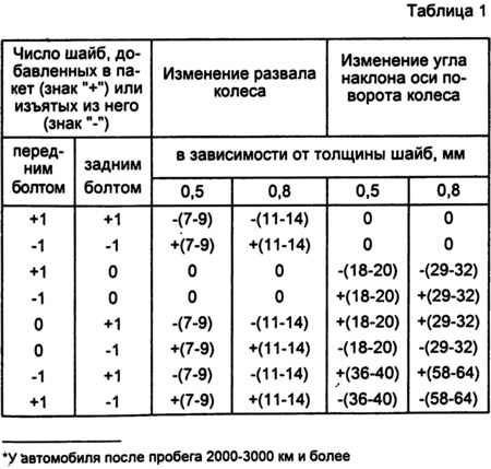
The change in the value of the camber angle and the longitudinal inclination of the axis of rotation of the wheel depending on the thickness and the number of withdrawn or added washers 43 are shown in table 1.
Transverse angle (γ) the inclination of the axis of rotation of the wheel is not adjustable, as it is set constructively.