




The joints can be replaced either directly on the vehicle or on the levers removed from the vehicle (see subsection 8.1.6).
Replacing rubber-metal hinges of lower arms
1. Place the car on a ditch or lift and lift the front of the car on the side where the replacement will be made. Remove the wheel.
2. After unscrewing the nut, press out the ball joint pin of the steering rod using puller A.47052 and move the free end of the side rod back.
3. Loosen the nuts securing the lower control arm to the axle and remove the washers from both ends of the axle.
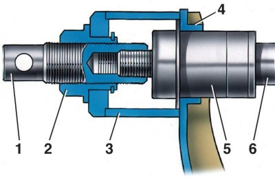
4. Install cup 3 of device 02.7823.9500 on the shelf of lever 4 and screw screw 1 onto the end of axis 6 (2 – nut, 5 – hinge).
5. Holding screw 1 with a handle and turning nut 2, move the lever eye from the outer ring of the hinge. Remove the device and the pressed-out hinge 5 from the lever axis.
6. Using a crowbar or tire iron, position the lever eye so that it is concentric with the lever axis, insert the new hinge into the hole in the lever eye and place it on the axis.
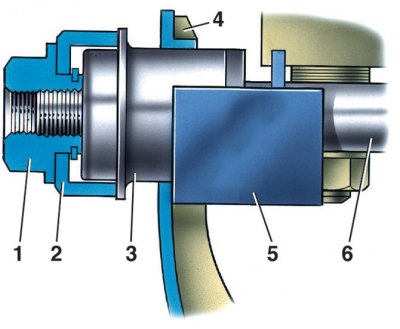
7. Place ring 2 of device 02.7823.9501 on the end of the axle and insert stop 5 between shelf 4 and the nearest nut securing the axle to the front suspension crossmember (1 – nut; 3 – hinge; 4 – lower arm; 6 – lower arm axis).
8. Rotate nut 1 and hold stop 5, press new joint 3 into the lever eye. Remove the device, install the washer and nut for fastening the lever to the axle. Do not tighten the nut.
9. Similarly, other rubber-metal joints of the lower suspension arms are replaced.
10. After replacing the joints, connect the steering rod to the steering knuckle arm, tighten and cotter pin the steering rod ball joint nut, install and secure the wheel.
Replacing rubber-metal hinges of upper arms
Replace the rubber-metal joints of the upper suspension arms using the A.47046 tool in the same way as on the removed arms (see subsection 8.1.6), in the following order.
1. Place the vehicle on an inspection pit or lift.
2. Use a jack to raise the front of the vehicle on the side where the replacement will be performed.
3. Remove the wheel.
4. Unscrew the nut of the upper arm axle and, having removed the axle, turn the arm with the eyes outward.
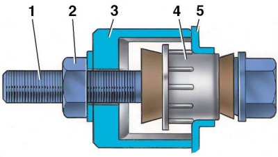
5. Install cup 3 of device A.47046 with nut 2 and bolt 1 with the head inside the lever on the lever. Rotate nut 2, press out joint 4, remove the device and joint (5 - upper lever).
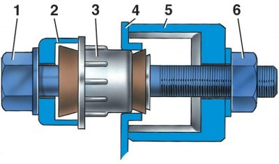
6. Insert the new joint into the eye of the lever, install the device A.47046 so that the head of the bolt 1 is directed outward and there is ring 2 of the device A.47046 under the head. Rotating nut 6, press in the joint 3 and remove the device (4 - upper lever, 5 - cup of the device A.47046).
7. The other joints of the upper arms of the front suspension are replaced in a similar manner.
8. After replacing the hinges, turn the upper arm with the eyes towards the front pillar, slide it onto the pillar, insert the upper arm axle, install the washer and axle nut without tightening it completely.
9. Install the wheels, lower the vehicle and tighten the control arm axle nuts. Before tightening the nuts, perform all the operations described earlier (see subsection 8.1.4).
10. After replacement, the rubber-metal joints should be "warmed up" by taking a test drive of 15–20 km, and it is imperative to check and, if necessary, adjust the installation angles of the front wheels.