
Suspension arms
The deformation of the upper and lower arms is determined on fixture A.95716.
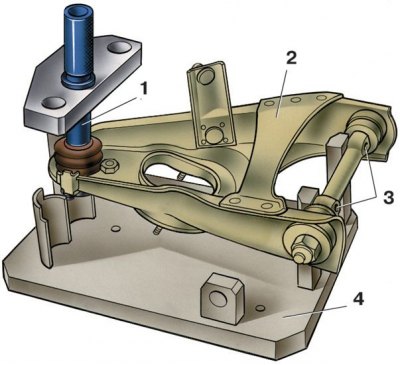
1. Install the lower arm so that the mandrel 1 for centering articulates with the taper of the pin of the ball joint of the lever, and the locating pins of the tool 4 (device A.95716 for checking levers) entered the holes 3 of the axis of the lever 2.
2. The centering mandrel must enter, respectively, into the right or center hole of the device, depending on which lever is being checked, right or left.
3. A sign of the deformation of the lever is the impossibility of inserting the device into the holes 3 of the lever axis without the effort of the fingers, as well as poor articulation of the mandrel 1 with the cone of the ball joint pin.
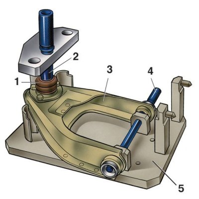
4. Upper arm 3 is mounted on fixture 5 (fixture A.95716) in an inverted position so that the mandrel 2 for centering the ball joint exactly coincides with the shank of the pin of the ball joint 1, and the pin 4 passes into the holes of the rubber-metal joints of the lever.
5. The magnitude of the deformation of the lever is determined by the difficulty of inserting the pin 4 into the holes of the levers and by the poor articulation of the conical seat of the mandrel 2 with the conical surface of the pin of the ball joint 1. The pin 4 should enter the holes of the hinges without much effort.
6. With a small deformation, the levers are corrected, and with a large one, they are replaced.
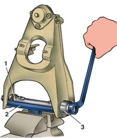
Ball joints
Checking the upper ball joint on tool 02.8701.9502
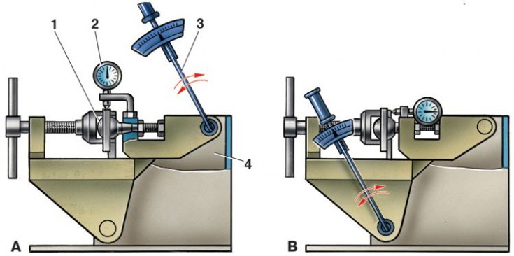
1 - ball joint; 2 - indicator; 3 - torque wrench; 4 - fixture 02.8701.9502; A - scheme for checking the radial clearance; B - scheme for checking the axial clearance
1. Make sure that the mudguards of the hinges are intact. Breaks, cracks, delamination of rubber from metal fittings, traces of lubricant leakage are unacceptable.
2. Check for wear on the running surfaces of the ball joints by manually turning the ball pin. Free movement of the finger or its sticking is unacceptable.
3. A more accurate check of the condition of the upper ball joint by the value of the radial and axial clearance is carried out on the fixture 02.8701.9502. To do this, install the ball joint 1 (drawing A) into the socket of the fixture and tighten it with a screw. Install indicator 2 in the fixture bracket so that its leg rests against the side surface of the hinge body, and the indicator needle is at zero.
4. Install the torque wrench 3 in the upper socket of the tool and apply a torque of 196 Nm to it (20 kgf·m) in both directions, use indicator 2 to determine the total radial clearance in the ball joint. If it exceeds 0.7 mm, replace the hinge with a new one.
5. Similarly, the axial clearance in the ball joint is checked, having previously changed its fastening in the fixture, as shown in Figure B. The axial clearance in the hinge is allowed no more than 0.7 mm.
Rubber-metal hinges
Signs in which it is necessary to replace the rubber-metal joints are described (see subsection 8.1.2).
The replacement procedure is as follows.
Replacement
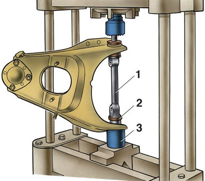
1. Install the lower lever on the mandrel 3 and press the lever axis 1 with the press punch until the hinge 2 is pressed out of the hole. To press out the second hinge, turn the lever over and repeat the operation.
2. Pressing in the hinges of the lower levers is carried out using the spacer sleeve A.74177/2, clamped in a vice, and fixture A.74177/1. Install the lever with axle 1 on tool 2, put the hinge on the axle and press it into the lever seat using tool 3 (А.74177/1). Then repeat the above steps to press in the second pivot on the other side of the arm.
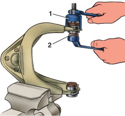
3. Upper lever. To press out the hinges, install tool A.47046 on the lever so that the screw head of tool 1 points inward. By tightening the screw of the device, press out the hinge 2.
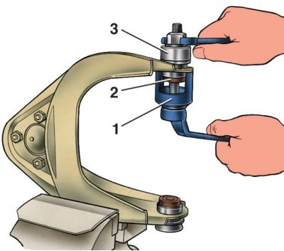
4. To press fit, insert hinge 2 into the lever seat and install tool A.47046, complete with cap 3. Turning the screw of tool 1, press the hinge into the lever seat.
Steering knuckles
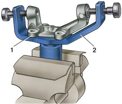
1. To check, install the steering knuckle 1 on the caliber 2 A.96008, clamped in a vice so that its surface under the wheel hub seal coincides with the caliber hole.
2. Insert the two side gauge pins into the knuckle holes. If the insertion of the fingers requires some effort, then the fist is deformed and must be replaced with a new one.
Suspension springs
Basic data for checking the front suspension springs
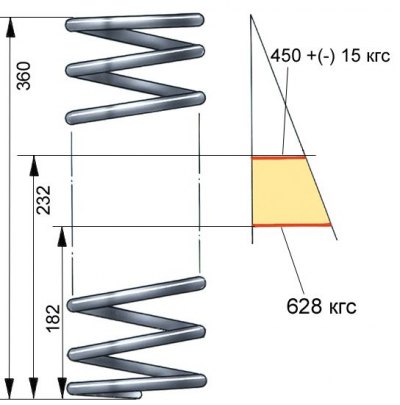
Carefully inspect the springs. If deformations are found that may cause a malfunction, replace the springs with new ones.
1. Compressing the spring three times until the coils touch, check its elastic characteristic according to the control points.
2. Check the technical condition of the insulating gaskets and replace them if they are damaged.
Attention! Lengthwise, under load 4413 N (450 kgf), the springs are divided into two groups: group A - the length is greater than 232 mm and group B - the length is equal to or less than 232 mm. Group A springs are marked with yellow paint, and group B - green, on the outside of the coils. The marking should be clearly visible after installing the spring on the car.
Stabilizer bar
1. Check if the rod is deformed and if its ends are in the same plane; if the deformation is insignificant, then straighten the bar; If there is significant deformation, replace the rod.
2. Check the safety of the pillows in the mounting brackets to the body and to the lower suspension arms; when worn, replace the pads.
Front suspension crossbar
Checking the front suspension cross member
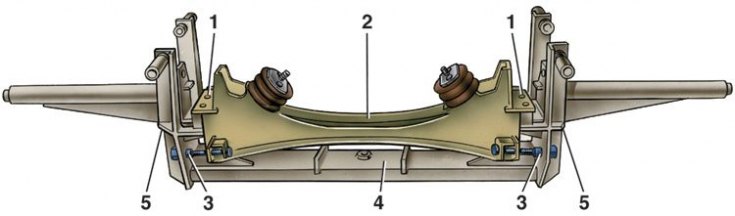
1 - a hole on the cross member for the mounting pins of the fixture; 2 - cross member; 3 - control bushings of the device; 4 - fixture А.78124/R; 5 - control holes for installing bolts on the cross member
1. To check, install the cross member on fixture 4 so that the pins match the holes 1 of the cross member.
2. Screw on the ends of the two bolts of the cross member control bushings 3 adaptations.
3. Holes 5 of the fixture and the bolts of the cross member opposite them must be aligned.
4. Signs of deformation of the cross member - the impossibility of inserting without force the pins of the device into the holes of the cross member, the misalignment of the bolts of the cross member with the bushings 3 of the device. If a deformation is found that cannot be corrected by straightening, replace the cross member.