




Starter parts
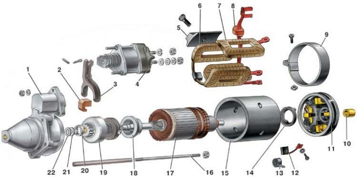
1 – starter cover on the drive side; 2 – rubber plug; 3 – drive lever; 4 – traction relay; 5 – stator pole; 6 – stator winding service coil; 7 – shunt coil of the stator winding; 8 – rubber plug; 9 – protective tape; 10 – cover bushing; 11 – cover from the collector side; 12 – brush; 13 – brush spring; 14 – brake disc cover; 15 – body; 16 – tie rod; 17 - anchor; 18 – gear travel limiter; 19 – overrunning clutch with drive gear; 20 – limiting ring; 21 – thrust washer; 22 – adjusting washer
Starter Rear Parts 35.3708
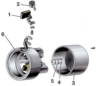
1 – brush; 2 – brush spring; 3 – protective cover; 4 – lock washer; 5 – adjusting washer; 6 – cover from the collector side
1. Loosen the nut on the lower contact bolt of the traction relay and disconnect the stator winding terminal from it.
2. Loosen the nuts securing the traction relay and remove it.
3. For the ST-221 starter, loosen the screw securing the protective clamping tape on the cover 11 (see fig. Starter parts) from the collector side and remove tape 9 with the gasket. Unscrew the screws securing the brush terminals and remove the brushes.
(The original can be seen on the website VAZbook.ru)
4. For starter 35.3708, unscrew the screws and remove the protective cover 3 (see fig. Starter rear parts 35.3708). Loosen the screws securing the stator winding terminals to the brush holders, remove springs 2 and brushes 1. Remove lock washer 4.
5. At the starter ST-221 (see fig. Starter parts) unscrew the nuts of the tie rods 16 (on starter 35.3708 unscrew the tie bolts) and disconnect the housing 15 with the cover 11 from the cover 1 with the anchor 17. Unscrew the tie rods from the cover 1. Disconnect the cover from the collector side from the housing.
6. Remove the rubber plug 2 of the lever from the cover on the drive side. Unpin and remove the axle of the lever 3 of the starter drive from the cover. Remove the lever and the anchor with the drive from the cover, and then disconnect the lever from the drive.
7. To remove the drive from the anchor, remove the retaining ring from under the limiting ring 20. The drive is disassembled after removing the retaining washer from the coupling hub.
8. If the traction relay is made in a disassemblable design, i.e. the relay parts are not crimped into its housing, then to disassemble it, unscrew the nuts of the tie bolts and unsolder the winding terminals from the "50" plug and from the tip secured to the lower contact bolt of the traction relay.
9. After disassembling, blow out the parts with compressed air and wipe them dry.