
Anchor
1. Check with a megger or with a lamp powered by 220 V for a short circuit of the armature winding to ground.
2. Voltage through the lamp is supplied to the collector plates and to the armature core. The burning of the lamp indicates the closure of the collector plates with the ground. When checking, the megger must show a resistance of at least 10 kOhm. Replace the anchor that has a short to ground.
3. Using a special device, check for short circuits between the sections of the armature winding and the collector plates, and also for breaks in the place where the leads of the winding sections are soldered to the collector plates.
4. Inspect the working surface of the collector. Clean the dirty or burnt surface with a fine-grained sandpaper.
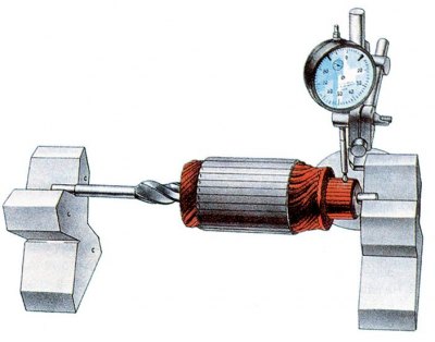
5. At the ST-221 starter, check the beating of the collector relative to the shaft trunnions.
6. If the runout is greater than 0.06 mm, and also if the surface of the collector is significantly damaged, turn the collector on a lathe, removing as little metal as possible. The minimum diameter to which the collector can be machined is 36 mm. After turning, sand the collector with fine-grained sandpaper.
7. Check core runout against shaft trunnions. If it is more than 0.08 mm, replace the anchor.
8. Check the condition of the surfaces of the splines and trunnions of the armature shaft. They should not have scuffs, nicks and wear.
9. If there are yellow marks on the surface of the shaft from the gear bush, remove them with fine-grained sandpaper, as they can cause the gear to seize on the shaft.
Drive unit
1. Gear teeth should not show significant wear. If there are nicks on the lead-in part of the teeth, then grind them with a fine-grained emery wheel of small diameter. The gear should turn easily relative to the clutch hub, but only in the direction of rotation of the armature when starting the engine.
2. If drive parts are damaged or severely worn, replace the drive with a new one.
Stator
1. Check with a megger or with a lamp powered by 220 V for a short to ground in the stator winding. The voltage through the lamp is supplied to the common terminal of the winding and to the starter housing.
2. If the lamp is on or the megger shows a resistance of less than 10 kOhm, and also if the windings show signs of overheating (insulation blackening), replace the case with windings.
Lids
1. Check the covers for cracks. If they are, replace the caps with new ones.
2. Check the condition of the cover bushings. If worn, replace cap assemblies or bushings only. Expand new bushings after pressing in to 12.015±0.03 mm.
3. For the ST-221 starter, to replace the bushing on the collector side, first remove the plug, and after pressing the bushing, put the plug back in place and drill out at three points.
4. Check the reliability of the fastening of the brush holders on the cover from the side of the collector. Brush holders of positive brushes must not have a short circuit with ground. The brushes must move freely in the grooves of the brush holders. Replace brushes worn in height up to 12 mm with new ones, after rubbing them against the collector.
Traction relay
1. Check the ease of movement of the relay armature. Check with an ohmmeter whether the contact bolts of the relay are closed by the contact plate. Check with an ohmmeter if there is an open in the windings of the traction relay.
2. If there is an open in the relay windings or the contact bolts of the relay do not close with a contact plate, then replace the relay with a new one.
3. If the relay is of a collapsible design, then you can disassemble it and clean the contact bolts and the plate with a fine-grained sandpaper or a flat velvet file. In case of significant damage to the contact bolts at the point of contact with the contact plate, the bolts can be turned by 180°.