




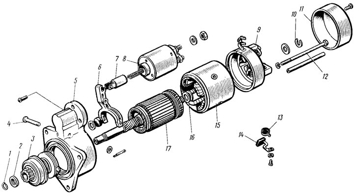
Figure 136. Starter parts: 1 - retaining ring; 2 - limiting ring; 3 - drive with freewheel clutch; 4 - lever axis; 5 - front cover; 6 - drive lever; 7 - relay anchor; 8 - traction relay; 9 - back cover; 10 - lock washer; 11 - protective cover; 12 - tension bolt; 13 - brush spring; 14 - brush 15 - body; 16 - adjusting washers; 17 - anchor
Unscrew the screws and remove the protective casing 11. Remove the lock washer 10, unscrew the tie bolts 12 and disconnect the housing 15 with the rear cover 9 from the front cover 5 with the anchor 17. Unscrew the screws securing the stator winding terminals to the brush holders and disconnect the housing from the rear cover. Remove the springs 13 and brushes 14.
Remove the locking 1 and limiting 2 rings and disconnect the anchor from the drive 3. Unpin and remove the axle 4 of the lever from the front cover. Disconnect the lever 6 from the drive and remove the drive 3 from the front cover. The drive is disassembled after removing the lock washer from the coupling hub.
To disassemble the traction relay, unscrew the screws securing its cover and unsolder the winding terminals from the "50" plug and from the tip secured to the lower contact bolt of the traction relay.
After disassembling, the parts are blown with compressed air and wiped.
Before assembly, lubricate the helical splines of the anchor shaft and the freewheel clutch hub, the gear and the rear cover bushing with engine oil. Lubricate the drive ring with Litol-24 consistent grease.
The starter assembly is performed in the reverse order of disassembly. By selecting adjusting washers 16, the axial free travel of the anchor is provided within 0.07-0.70 mm. An insulating plastic tube is put on the tension bolt passing near the stator winding terminals.
After assembly, the starter is tested on a stand.
The text is published on the portal (VAZbook.ru)