
Checking the axial clearance of the crankshaft
The axial movement of the crankshaft is limited by two thrust half rings mounted on both sides of the rear main bearing. A steel-aluminum half ring is installed on the front side of the bearing, and a metal-ceramic semi-ring on the back side (yellow color). Half rings are made of normal thickness (2.310–2.360 mm) and increased (2.437–2.487 mm).
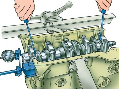
1. The axial clearance between the thrust half rings and the thrust surfaces of the crankshaft is checked as follows:
- install the indicator on the magnetic stand and insert the ends of two screwdrivers as shown in the figure;
- move the shaft with screwdrivers and check the axial clearance on the indicator, which should be in the range of 0.06–0.26 mm.
2. If the gap exceeds the maximum allowable 0.35 mm, replace the thrust half rings with others increased by 0.127 mm.
Attention! The axial clearance of the crankshaft can also be checked on the engine installed on the vehicle using tool 67.8701.9510. In this case, the axial movement of the crankshaft is created by pressing and releasing the clutch pedal, and the value of the axial clearance is determined by the movement of the front ring of the crankshaft.