




Contents: Examination ↓ Grinding of necks ↓
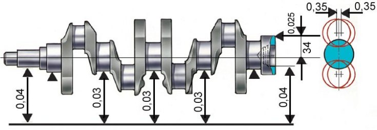
Permissible runout of the main surfaces of the crankshaft
Examination
1. Install the crankshaft on two prisms (see fig. Permissible runout of the main surfaces of the crankshaft) and check with the indicator:
- beating of main journals (maximum allowable 0.03 mm);
- runout of the seating surfaces under the sprocket and bearing of the primary shaft of the gearbox (maximum allowable 0.04 mm);
- displacement of the axes of the connecting rod journals from the plane passing through the axes of the connecting rod and main journals (maximum permissible ±0.35 mm);
- non-perpendicularity of the flange end surface to the crankshaft axis. When turning the shaft, an indicator mounted on the side at a distance of 34 mm (see fig. Permissible runout of the main surfaces of the crankshaft) from the shaft axis, should not show a runout of more than 0.025 mm.
2. Cracks are not allowed on the main and connecting rod journals and on the crankshaft cheeks. If they are found, replace the shaft.
3. No scratches, nicks or grooves are allowed on the surfaces of the crankshaft that are mated with the working edges of the seals.
4. Measure the diameters of the main and connecting rod journals. The journals should be ground if their wear is more than 0.03 mm or the ovality of the journals is more than 0.03 mm, and also if there are burrs and scratches on the journals.
Grinding of necks
1. Grind the main and connecting rod journals, reducing by 0.25 mm so as to obtain, depending on the degree of wear, diameters corresponding to the values given in Table. Connecting rod journal diameters, mm and Table. Main journal diameters, mm, and the journal fillet radii, as shown in Fig. Main dimensions of connecting rod and main journals of the crankshaft and their fillets.
2. After grinding and subsequent finishing of the journals, rinse the crankshaft thoroughly to remove any remaining abrasive. Rinse the lubrication channels with the plugs removed several times with gasoline under pressure. Mark the reduction value of the main and connecting rod journals on the first cheek of the crankshaft (for example, K 0.25, W 0.50).
3. The ovality and taper of the main and connecting rod journals after grinding should be no more than 0.007 mm.
Diameters of connecting rod journals, mm
Nominal | Reduced | |||
0,25 | 0,50 | 0,75 | 1,0 | |
47,814 | 47,564 | 47,314 | 47,064 | 46,814 |
47,834 | 47,584 | 47,334 | 47,084 | 46,834 |
Main journal diameters, mm
Nominal | Reduced | |||
0,25 | 0,50 | 0,75 | 1,0 | |
50,775 | 50,525 | 50,275 | 50,025 | 49,775 |
50,795 | 50,545 | 50,295 | 50,045 | 49,795 |