
Preliminary check
1. Before installing the ignition distributor on the stand, check the condition of the breaker contacts (whether the lever with a moving contact sticks on the axis) and the pressing force of the contacts, which should be 4.9–5.88 N (500–600 gs).
2. Check the wear of the textolite block of the breaker lever. In case of wear, set the required gap between the breaker contacts. If the lever sticks on the axis or its spring is weakened, replace the contact group.
3. If the breaker contacts are dirty, burnt, or eroded, clean them with a velvet file. Grinding paper and other abrasive materials cannot be used for this purpose.
4. After stripping, wipe the breaker contacts with chamois soaked in gasoline. Then pull back on the lever to let the gasoline evaporate, and wipe the contacts again with dry chamois leather. Instead of suede, you can use any material that does not leave fibers.
5. Contacts must be in contact with the entire surface. If this does not happen, then, bending the rack bracket, adjust the position of the fixed contact. It is impossible to bend the lever with a movable contact.
6. Wipe off the ignition distributor cap from dirt and oil.
7. Slightly lifting the cover of the ignition distributor, check if the contact of the rotor is against the electrode of the cover at the moment the breaker contacts open.
Checking work
1. Install the ignition distributor on the test bench for testing ignition devices and connect it to the electric motor, the speed of which is adjustable.
2. Make connections to the ignition coil and to the stand battery (see fig. Scheme of the ignition system). Connect the four terminals of the cover to spark gaps, the gap between the electrodes of which is adjustable.
3. Set a gap of 5 mm between the electrodes of the arresters, turn on the electric motor of the stand and rotate the ignition distributor shaft for several minutes clockwise at a frequency of 2000 min–1. Then increase the gap between the electrodes to 10 mm and watch for internal discharges in the distributor. They are detected by sound or by the weakening and interruption of sparking on the arrester of the test bench.
4. During operation, the ignition distributor should not produce significant noise at any speed of the roller.
Removing the characteristics of automatic ignition advance
Characteristics of the centrifugal regulator
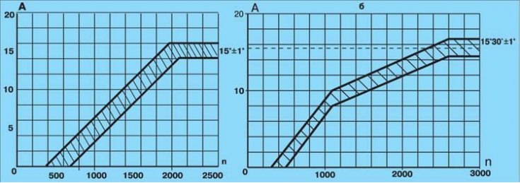
a - ignition distributor R-125;
b - ignition distributor 30.3706-01;
А – ignition advance angle, deg;
n - rotational speed of the ignition distributor roller, min–1
1. Install the ignition distributor on the stand and make electrical connections in accordance with the instructions for the stand. Set a gap of 7 mm between the spark gap electrodes.
2. Turn on the electric motor of the stand and rotate the ignition distributor roller at a frequency of 150–200 min–1. On the graduated disk of the stand, note the value in degrees at which one of the four sparks is observed.
3. Increasing the speed in steps by 200–300 min–1, determine from the disk the number of degrees of ignition advance corresponding to each frequency of rotation of the ignition distributor roller.
4. Compare the obtained characteristic of the centrifugal ignition timing controller with the characteristic in fig. Characteristics of the centrifugal regulator.
5. If the characteristic differs from that shown in the figure, then it can be brought back to normal by bending the spring racks of the weights of the centrifugal regulator. Up to 1100 min–1 - bend the rack of a thin spring, and over 1100 min–1 - thick. To decrease the angle, increase the tension of the springs, and to increase, decrease.
Removal of the characteristics of the vacuum regulator of an advancing of ignition
Characteristics of the vacuum regulator of the ignition distributor 30.3706-01
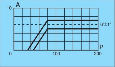
A - ignition timing; R - rarefaction, mm. rt. Art.
1. Install the ignition distributor on the stand and make connections in accordance with the instructions for the stand.
2. Turn on the electric motor of the stand and rotate the ignition distributor shaft with a frequency of 1000 min–1. On the graduated disk, note the value in degrees at which one of the four sparks occurs.
3. Gradually increasing the vacuum, every 20 mm Hg. Art. note the number of degrees of ignition advance relative to the original value.
4. Compare the resulting characteristic with the characteristic in Fig. Characteristics of the vacuum regulator of the ignition distributor 30.3706-01. Pay attention to the clarity of the return to its original position after removing the vacuum of the moving plate 26 (see fig. Ignition distributor 30.3706-01) breaker.
Checking the angle of the closed state of the contacts
1. Install the distributor on the test bench and remove the cover from it. Make connections in accordance with the instructions for the stand.
2. Turn on the electric motor of the stand and bring the rotational speed of the ignition distributor roller to 1000 min–1.
3. On the illuminated parts of the scale, measure the angle of the closed state of the contacts, which should be 55±3°.
4. Then check the angles between the opening moments of the contacts on the cylinders relative to the first (asynchronism), which should not differ from the nominal by more than±1°.
Insulation resistance test
The insulation resistance between the various terminals and ground should be checked with a megger. Measure the resistance between the low-voltage terminal of the breaker and ground with the breaker contacts open. Insulation resistance at 25±5°C must be at least 10 MΩ.
Capacitor check
Capacitor capacitance, measured in the frequency range between 50 and 1000 Hz, should be in the range of 0.20-0.25 µF.