
Ignition switch
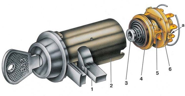
1 - locking rod; 2 – the case of the ignition switch; 3 - roller; 4 - contact disk; 5 - contact sleeve; 6 - block; a - wide protrusion of the contact part
At the ignition switch, the operation of the anti-theft device is checked and the correct closure of the contacts at various key positions (see table. Switching of terminals of the ignition switch). Voltage from the battery and generator is supplied to the contacts «30» and «30/1». free plug «INT» used to connect the radio.
The locking rod of the anti-theft device must extend when the key is set to position III (parking) and take it out of the castle. The locking rod must retract after turning the key from position III to position 0 (turned off). The key must only be removed from the lock in position III.
When installing the contact part in the circuit breaker housing, it must be positioned so that the plugs «15» and «30» were on the side of the locking rod 1 (see fig. ignition switch), while a wide protrusion «A» the contact part will fit into the wide groove of the ignition switch housing.
Switching of terminals of the ignition switch
Key position | Single voltage contacts | Switched circuits |
0 (Turned off) | 30 and 30/1 | – |
I (Ignition) | 30–INT | Outdoor Lighting. Windshield wiper and washer. heater |
30/1–15 | The excitation winding of the generator. Ignition system. Direction indicators. Control devices. reversing light | |
II (Starter) | 30–INT | See position I |
30/1–15 | See position I | |
30–50 | Starter | |
III (Parking) | 30–INT | See position I |