




Ignition system diagram
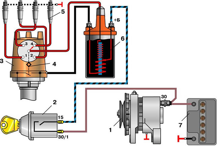
1 – generator; 2 – ignition switch; 3 – ignition distributor; 4 – breaker cam; 5 – spark plugs; 6 – ignition coil; 7 – battery
Ignition distributor R-125
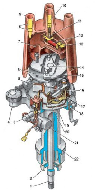
1 – roller; 2 – oil-deflecting clutch; 3 – roller oiler; 4 – octane corrector eccentric; 5 – felt; 6 – centrifugal regulator support plate; 7 – rotor; 8 – side electrode with terminal; 9 – lid; 10 – central electrode with terminal; 11 – central electrode carbon; 12 – resistor; 13 – outer rotor contact; 14 – centrifugal regulator plate; 15 – weight; 16 – breaker cam; 17 – contact group; 18 – contact group fastening screw; 19 – movable breaker plate; 20 – groove; 21 – capacitor; 22 – ignition distributor housing
Ignition distributor 30.3706-01
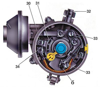
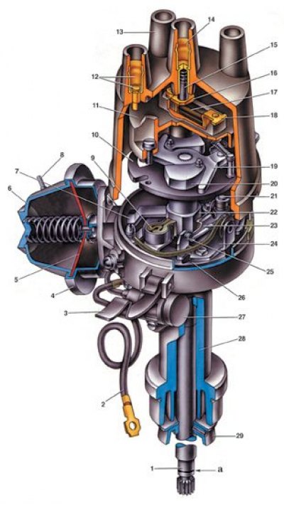
1 – ignition distributor shaft; 2 – wire for supplying current to the ignition distributor; 3 – cover fastening latch; 4 – vacuum regulator housing; 5 – diaphragm; 6 – vacuum regulator cover; 7 – vacuum regulator rod; 8 – vacuum hose connection from carburetor; 9 - cam oil wick (filz); 10 – ignition timing regulator support plate; 11 – ignition distributor rotor; 12 – side electrode with terminal for wire to spark plug; 13 – distributor cap; 14 – central terminal for wire from ignition coil; 15 – central carbon electrode with spring; 16 – central contact of the rotor; 17 – resistor for suppressing radio interference; 18 – outer rotor contact; 19 – leading plate of the centrifugal regulator; 20 – centrifugal ignition timing adjuster weight; 21 – lever axis; 22 – breaker cam; 23 – breaker lever; 24 – rack with breaker contacts; 25 – breaker contacts; 26 – movable breaker plate; 27 – capacitor; 28 – ignition distributor housing; 29 – oil-deflecting clutch of the shaft; 30 – bearing retainer plate; 31 – breaker movable plate bearing; 32 – oiler body; 33 – screws for fastening the stand with breaker contacts; 34 – terminal clamp screw; a – groove for distinguishing ignition distributors 30.3706; b – groove for moving the rack with contacts
Until 1980, the VAZ-2101, -2102 cars used the R-125 ignition distributor. It was installed on engines with old 2101 type carburetors. This ignition distributor had an octane corrector 4, which could be used to change the ignition timing within small limits.
Since 1980, when the engines began to be equipped with 2105-1107010 carburetors (type "Ozon"), the 30.3706-01 ignition distributor with a vacuum ignition timing regulator was installed. During the transition period, the 30.3706-83 ignition distributor was also produced, which could be installed on engines with old carburetors. It did not have a vacuum regulator, and otherwise its design was similar to the 30.3706-01 ignition distributor.
There are also ignition distributors 30.3706, which have a longer shaft and are installed on engines 2103 and 2106. For distinction, ignition distributors 30.3706 have a groove "a" at the end of the shaft.