




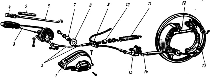
Fig. 206. Parking brake drive parts:
1 - case; 2 - front cable; 3 - lever; 4 - button; 5 - spring; 6 - latch rod; 7 - bushing; 8 - roller; 9 - rear cable guide; 10 - spacer sleeve; 11 - release spring; 12 - spacer bar; 13 - manual brake pad drive lever; 14 - rear cable; 15 - rear cable mounting bracket.
This lever is hinged to the brake shoe with a finger and rests against the groove of the spacer bar 8. The brake shoe enters the opposite groove of the bar.
When lever 11 is raised (see fig. 192), the front and rear drive cables are tensioned. In this case, lever 7 (see fig. 203), rotating on the pin, through the spacer bar 8, it will first press one shoe to the brake drum, and then, rotating relative to the point of contact with the spacer bar and acting as a two-arm lever, it will press the other shoe to the drum.
Information copied from the portal: www.VazBook.ru