
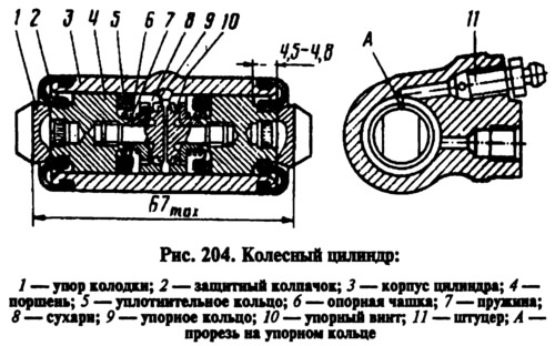
With an optimal clearance between the pads and the drum, during braking, the pads move apart to select a gap of 1.25-1.65 mm between the shoulder of the screw and the shoulder of the thrust ring. The specified gap allows the pads to travel to create maximum braking torque on the rear wheels.
When the pads are worn, the gap of 1.25-1.65 mm is completely eliminated, the collar on the stop screw is 10 (see fig. 204) is pressed against the shoulder of the ring 9, as a result of which the thrust ring is shifted after the piston by the amount of wear. With the cessation of braking, the pistons are shifted by the force of the coupling springs until the crackers stop against the shoulders of the thrust rings. In this way, the optimal clearance in the brake mechanism is maintained.
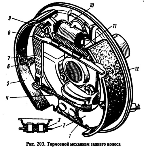
Brake mechanism drum type with self-aligning pads
Brake pads 5 and 2 (see fig. 203), wheel cylinder 10 and other parts of the brake mechanism are mounted on shield 12, which is attached to the flange of the rear axle beam. The pads with their lower part rest on plate 3, which is included in a package of plates riveted to the brake shield. The upper part of the pads go into the grooves of the stops of the pistons of the wheel cylinder. The pads are kept from axial displacement by springs mounted on racks 6. The lever 7 of the manual drive of the pads is pivotally connected to the rear brake pad, with a pin 9. Its rib enters the groove of the expander bar 8, into the opposite groove of which the front block 2 enters. Between themselves, the blocks are pulled together by springs 1 and 11.