
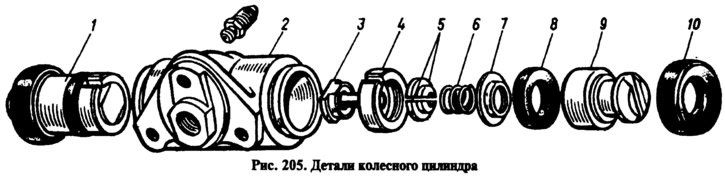
Turning the piston 9 with a screwdriver, unscrew the stop screw 3 from the piston. Remove the seal 8 from the screw with the support cup 7, the spring 6 and crackers 5. Separate the thrust ring 4 and the thrust screw 3.
Assemble the automatic device in reverse order, taking into account the following:
- tighten the thrust screws of the pistons with a torque of 0.4-0.7 kgf·m;
- slot A (see fig. 204) on the thrust rings should be directed vertically upwards, the deviation from the vertical is allowed no more than 30°. This arrangement of the slot provides a more complete removal of air from the rear brake drive when it is pumped;
- to pre-compress the thrust rings, press the pistons into the cylinder body using a special tool in the form of a cylinder with a conical inner hole;
- the force of pressing the piston into the cylinder must be at least 35 kgf; with a force of less than 35 kgf, replace the thrust ring;
- when pressing the piston into the cylinder, it is necessary to maintain the size of 4.5-4.8 mm and 67 mm (maximum) (see fig. 204) for free fit of the brake drum;
- Before installing parts in the cylinder body, lubricate them liberally with brake fluid. After assembly, check the movement of each piston in the cylinder. They should move easily within 1.25-1.65 mm. Replace protective caps 2 last.