
Mechanical drive includes 9 hand lever (see fig. 135), which is connected through the return lever and the pin with the front cable 19, the guide roller 18, the guide 2 (pic. 149), rear cable 17 (see fig. 135) with sheath, lever 1 (see fig. 146) manual drive of pads and spacer bar 13.
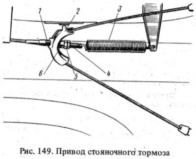
Front cable 1 (see fig. 149) has a threaded tip that goes through the hole in the rear cable guide 2. The tip of the front cable through the spring 3 is connected to the body bracket. This connection ensures that the drive cables return to their original position when the parking brake lever is released.
The middle part of the rear cable passes through the guide 2 groove, the tension of which is regulated by the nut 5, which is fixed by the lock nut 4. A spacer sleeve 6 is installed between the guide 2 and the nut 5. The ends of the rear cable pass through the sheath, each branch of which is attached at one end to the brake shield, and others are installed in the grooves of the body brackets. At the rear ends of the cable there are tips, each of which is connected to the hook of the lever 1 (see fig. 146) manual drive pads. This lever is pivotally attached to the brake shoe with a finger and abuts against the groove of the spacer bar 3. The rib of the brake shoe enters the opposite groove of the bar.
When lever 9 is lifted (see fig. 135), the front and rear parking brake cables are tensioned. In this case, lever 1 (see fig. 146), turning on the finger, through the spacer bar 3, will first press one shoe to the brake drum, and then, turning relative to the point of contact with the spacer bar and acting as a two-arm lever, will press the other shoe to the drum.