




Basic dimensions for checking the attachment points of units
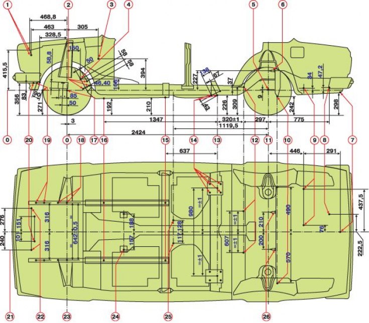
0 – baseline; 1 – Upper radiator mount; 2 – fastening of the steering gear housing and the pendulum arm; 3 – brake and clutch pedal axle; 4 – steering gear center; 5 – wheel center; 6 – rear suspension shock absorber mounts; 7 – center of the rear technological hole of the central reinforcement of the trunk floor; 8 – rear exhaust muffler mount; 9 – Front muffler mount; 10 – Rear suspension crossbar mount; 11 – rear wheel axle; 12 – axles of bolts for fastening the upper longitudinal rods of the rear suspension; 13 – axles of bolts for fastening the lower longitudinal rods to the body brackets; 14 – fastening of brackets of lower longitudinal rods; 15 – center of the rear technological hole of the front side member; 16 – center of the technological hole of the front side member; 17 – wheel center; 18 – Front suspension crossmember mounting points; 19 – anti-roll bar mount; 20 – lower radiator mount; 21 – car axle; 22 – Upper radiator mount; 23 – front wheel axle; 24 – Rear engine mount; 25 – fastening of the propeller shaft support; 26 – rear suspension shock absorber mounts
Checkpoints for checking the body floor
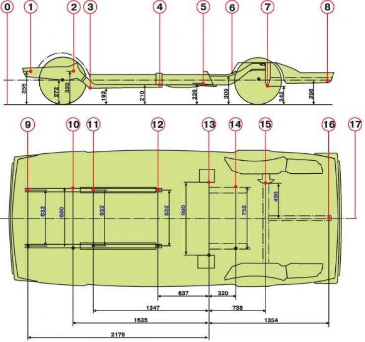
0 – reference line; 1 – intersection of the axes of the front anti-roll bar mounting bolts with the surfaces of the side members; 2 – center of the axes of the lower mounting bolts of the steering gear housing and the pendulum arm bracket; 3 – intersection of the centers of the front technological holes of the front floor with the surfaces of the side members; 4 – intersection of the rear technological holes of the front floor side members with the surfaces of the side members; 5 – center of the axes of the bolts for fastening the lower longitudinal rods; 6 – center of the axes of fastening of the upper longitudinal rods; 7 – intersection of the axis of the crossbar mounting bolt with the body bracket; 8 – intersection of the center of the rear technological hole of the central amplifier of the rear floor with the surface of the amplifier; 9 – center of the axles of the front anti-roll bar mounting bolts; 10 – intersection of the centers of the axes of the lower mounting bolts of the steering gear housing and the pendulum arm bracket with the surfaces of the side member mudguards; 11 – centers of the front technological holes of the front floor side members; 12 – centers of the rear technological holes of the front floor side members; 13 – intersection of the axes of the bolts securing the lower longitudinal rods with the outer surfaces of the body brackets; 14 – intersection of the axes of the bolts securing the upper longitudinal bars with the outer surfaces of the middle side members; 15 – intersection of the axis of the crossbar mounting bolt with the body bracket; 16 – center of the rear technological hole of the central reinforcement of the rear floor; 17 – longitudinal axis of the car
Installation for repair and inspection of bodies with a device for straightening
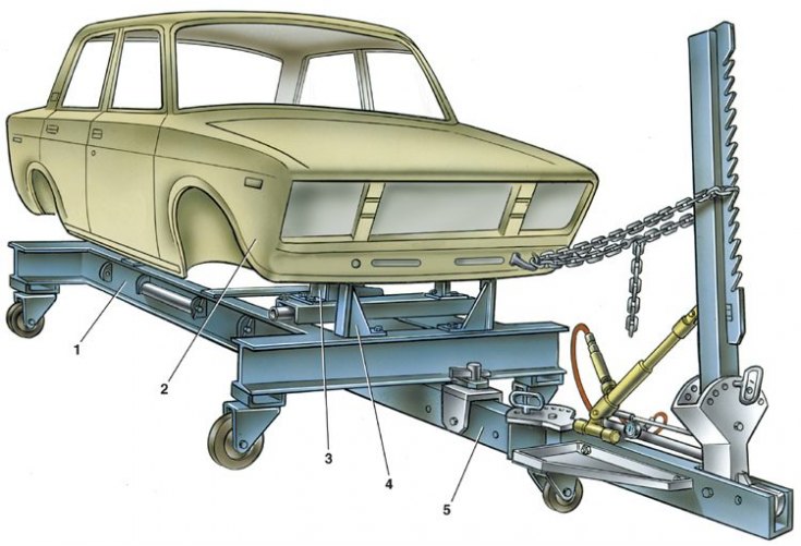
1 – installation frame: 2 – car body; 3 – Front suspension crossmember mounting bracket; 4 – anti-roll bar mounting bracket; 5 – straightening device with boom and hydraulic device
The article is taken from the website: VazBook
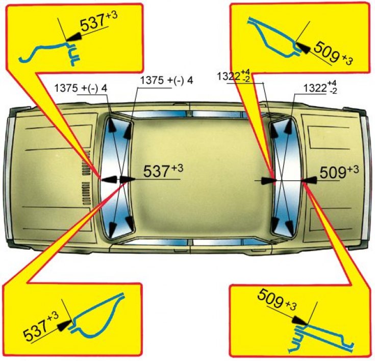
Reference linear dimensions of windshield and rear window openings
A significant portion of body repair work is carried out on damaged vehicles, which in most cases require checking the geometry of the attachment points of the vehicle chassis components and assemblies.
To check the geometry of the attachment points of the chassis units shown in Fig. Main dimensions of checking the attachment points of the units and Fig. Check points for checking the floor of the body, as well as to perform complex repairs with simultaneous control, a body repair and control unit is used in combination with straightening devices (see fig. Installation for repair and inspection of bodies with a device for straightening).
The straightening device is fixed to the frame on the side of the deformed part of the body.
The body damage can be very different. Therefore, the repair rules in each individual case should be their own, most suitable for these damages.
In almost all cases of damage, it is necessary to remove some parts to detect the damage, straighten and adjust the frame. In cases of severe damage, all easily removable interior trim parts are removed to facilitate measurement, inspection and installation of hydraulic or screw jacks to eliminate distortions and deflections.
The correction must restore the original linear dimensions of the body frame.
The diagonal dimensions of the window openings should be for the wind window (see fig. Reference linear dimensions of windshield and rear window openings) 1375±4 mm, for the rear – 1322+4 (1322–2) mm. The distances between the flanges of the window openings along the vehicle axis should be equal to 537 mm³ for the windshield and 509 mm³ for the rear window.
The difference in the diagonal dimensions of the windshield opening, as well as the openings of the rear window, hood, and trunk lid of the same body must not exceed 2 mm.
Most often, when repairing a frame, it is necessary to replace the wings, roof panels, front and rear. The methods for replacing and repairing these parts can be used as a basis for repairing other frame parts. It is also necessary to know the location of the welds.