




Open large image in new tab »
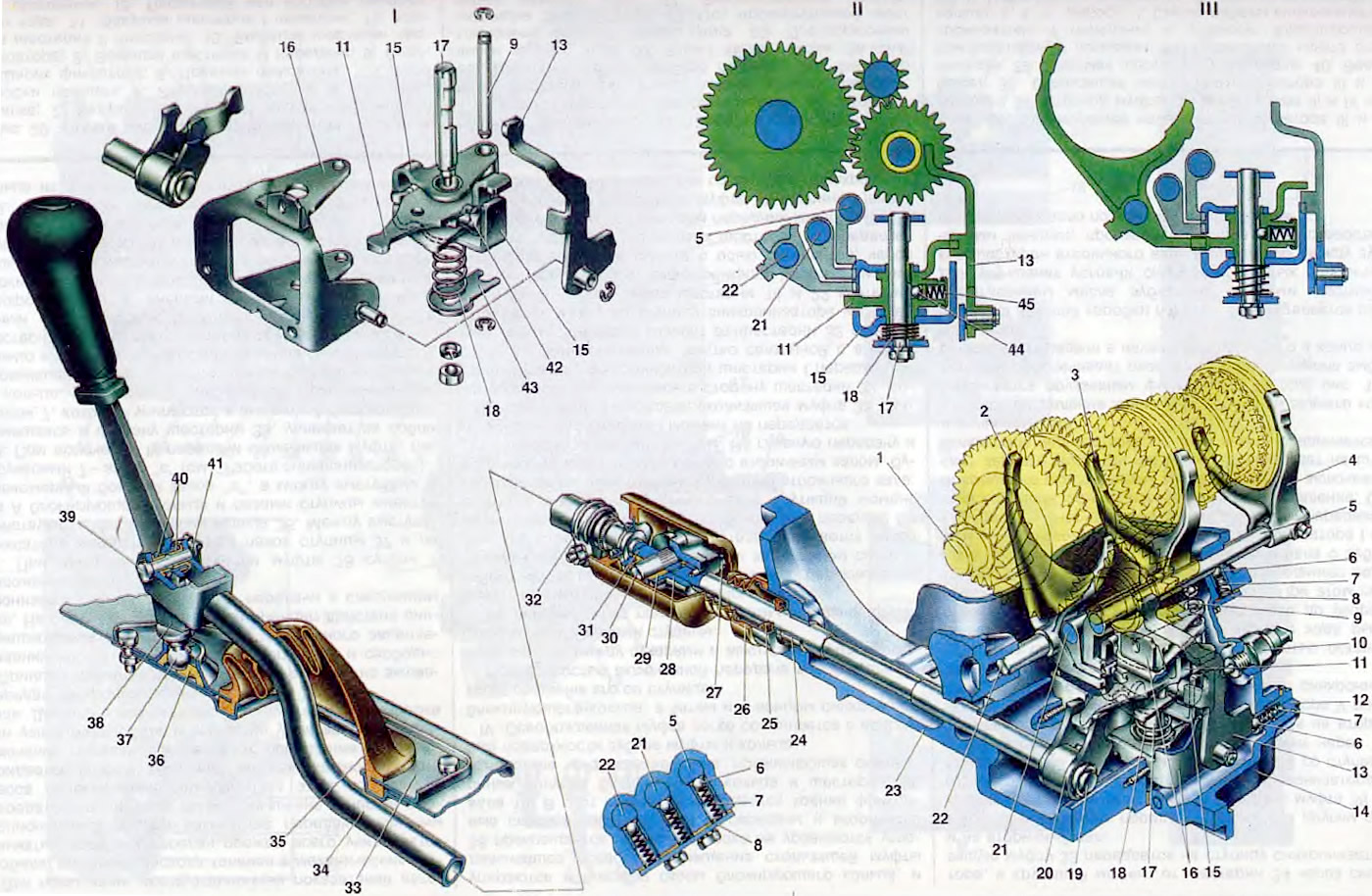
Figure 19. Gear shift drive: 1. Secondary shaft; 2. Fork for shifting 1st and 2nd gears; 3. Fork for shifting III and IV gears; 4. V gear engagement fork; 5. V-gear engagement fork rod; 6. Locking ball; 7. Lock spring; 8 Gear shift rod retainer cover; 9. Guide axis of the locking bracket; 10. Reverse light switch; 11. Three-arm gear selector lever; 12. Reverse gear fork lock plug; 13. Reverse gear fork; 14. Gearbox housing; 15. Locking bracket; 16. Gear selector housing; 17. Gear selector lever shaft; 18. Gear selector lever spring; 19. Gear selection rod; 20. Gear selector lever; 21. Shift fork rod for III and IV gears; 22. Shift fork rod for 1st and 2nd gears; 23. Clutch housing, 24. Bushing; 25. Gear selection rod seal; 26. Protective cover of the hinge; 27. Conical screw for fastening the hinge; 28. Gear shift rod hinge housing; 29. Hinge bushing; 30. Hinge axis; 31. Hinge tip; 32. Gear shift rod clamp; 33 Gear shift lever housing; 34. Gear shift drive rod; 35. Protective cover of gear shift rod; 36. Gear shift lever ball joint; 37. Gear shift lever spherical pin; 38. Gear shift lever; 39. Gear shift lever shaft; 40. Gear shift lever axle bushing; 41. Locking bracket; 42. Gear selector lever lock; 43. Gear selector lever thrust washer; 44 Gear selector lever locking ball; 45. Lock spring; I. Gear selection mechanism details; II. Selecting reverse gear; III. Selecting the front code.
The gear shift drive consists of a lever 38 with a ball pin 37, a ball joint 36, a rod 34, a hinge, a gear selection rod 19 and gear selection and shift mechanisms.
Gear shift lever 38 is connected to rod 34 by axle 39, which passes through plastic bushings 40 and is locked by bracket 41. The ball head of the lever is located in the spherical socket of ball support 36, made of plastic. It has four radial slots to facilitate installation of the lever in the support. The support is located in the socket of housing 33 of the lever, which is attached to the floor of the body with bolts. Rod 34 is tubular, with a welded eye for connection with the gear shift lever. At the other end of the rod, a slot is made for fastening the hinge with clamp 32. The place where the rod exits under the floor of the body is sealed with cover 35. The hinge does not allow the transmission of forces to the drive from vibrations and movement of the power unit. It consists of a housing 28 and a tip 31, pivotally connected to each other by an axis 30. The housing of the hinge is fastened to the rod 19 by a conical screw 27, and the tip of the hinge is in the rod 34 by a clamp 32. For a strong connection, small splines are cut on the tip. The hinge is covered with a protective cover 26, which is fastened on one side by a flange on the tip of the hinge, and on the other - on the body of the oil seal 25. To prevent damage to the cover when moving the rod 19, corrugations are made on it. The rod 19 of the gear selection is installed in the holes of the clutch housing, and its outer end rests on the sleeve 24 and is sealed at the outlet by the oil seal 25. On the inner end of the rod, the lever 20 of the gear selection is fastened with a conical screw. It consists of a two-arm lever and a plate having a single hub. Between the short arm and the plate there is one arm of the three-arm lever 11 of the gear selection mechanism. Therefore, with the axial movement of the rod 19, the lever 11 rotates on its axis. The long arm of the lever 20 of the gear selection rod also interacts with the lever 11, but moves it along the axis.
The gear selection mechanism is made as a separate unit secured with three bolts on the clutch housing. It consists of a housing 16, a three-arm gear selection lever 11, a gear selection lever axis 17, two locking brackets 15, an axis 9 of the locking brackets, a fork 13 for engaging reverse gear, a spring 18, and a thrust washer 43. Two axles 17 and 9 are secured to the housing 16 of the gear selection mechanism: one with a nut, the other with locking rings. A spring 18 is mounted on axis 17. The three-arm lever 11 and the locking brackets 15 have a single hub. Axis 9 passes through the holes in the hub, fixing them from turning. A locking ball 44 is mounted in the hub of the three-arm lever. One arm of the three-arm lever serves to engage forward gears, the other - to engage reverse gear, and the third arm is acted on by lever 20 of the gear selection rod.
The locking brackets lock the forward gear shift fork rods when the reverse gear is engaged, and when the forward gear is engaged, the reverse gear fork and other forward gear rods. When the gear shift lever is in the neutral position, the spring 18 moves the lever 11 and the locking brackets 15 on the axles until the ball 44 of the locking device stops against the step of the axle 17. In this position, the brackets lock the reverse gear fork 13 with one end, entering its groove, and with the other end they lock the fork of the 1st and 2nd gears, as well as the rod of the 5th gear: the forward gear selection lever is set to the position of engaging the 3rd and 4th gears, i.e. the 3rd or 4th gear is selected. When the gear shift lever is moved longitudinally, one of the specified gears is engaged. When the gearshift lever is moved laterally towards the reverse gear, the rod 19 rotates on its supports and the long arm of the lever 20 moves the lever 11 and the locking brackets 15 on the axles. In this case, the spring 18 is compressed, one end of the bracket comes out of the groove of the reverse fork and the arm of the lever 11 enters the groove instead of it, and the other end of the bracket enters the groove of the rod of the third and fourth gears instead of the lever 11. Thus, the rods with the forks of the forward gears will be locked and only the reverse gear can be engaged.
The gearshift mechanism transmits the force from the gearshift lever to the synchronizer clutches and the intermediate reverse gear. It consists of rods 5, 21, 22 and forks 2, 3, 4, as well as ball locks. The rods are located in the gearbox sockets and are fixed in the neutral and engaged positions by ball locks 6, which are located in three channels and closed by a common cover. Forks 2, 3 and 4 are bolted to the rods, which cover the synchronizer clutches. The fork for shifting 1st and 2nd gears has a groove into which one shoulder enters when selecting gears (forward gear shift lever) three-arm gear selection lever. The III and IV gear rods have grooves for the selection lever in the bosses of the rods themselves. The reverse gear fork 13 is located on the axis of the gear selection mechanism housing and is locked on it with a lock washer. The reverse gear fork is fixed with a separate lock, into the socket of which the plug 12 is screwed. When reverse gear is engaged, the fork 13 acts on the rod of the reverse light switch 10, which is screwed into the gearbox housing. This closes the circuit of the reverse light lamp.
To ensure precise gear engagement, the drive adjustment is provided, for which: loosen the clamping bolt of clamp 32 and set the rod 19 to the neutral position. With the decorative cover raised, set the lever 38 so that its lower part is perpendicular to the body floor, and the handle is located from the right seat at a distance of 1/3 of the distance between the seats and tighten the nut of clamp 32.