




Open large image in new tab »
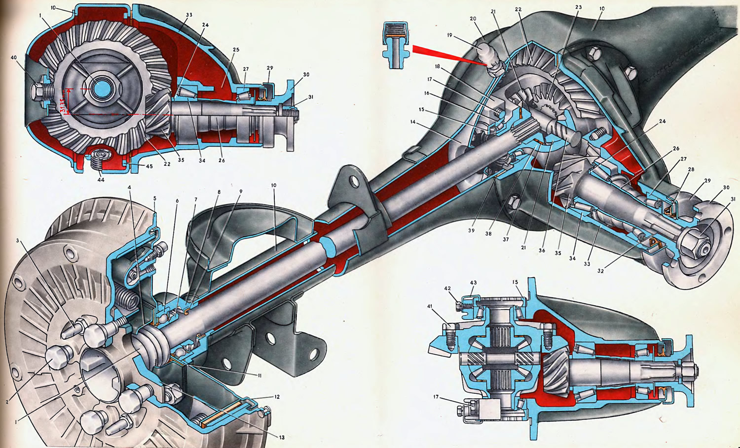
1. Axle shaft. 2. Brake drum and wheel fastening bolt. 3. Guide pin. 4. Oil deflector. 5. Brake drum. 6. Axle shaft bearing. 7. Locking ring. 8. Rear axle beam flange. 9. Oil seal. 10. Rear axle beam. 11. Thrust plate. 12. Rear brake shield. 13. Axle shaft flange. 14. Axle shaft guide. 15. Differential case bearing adjusting nut. 16. Differential case bearing. 17. Bearing cover fastening bolt. 18. Differential case bearing cover. 19. Breather. 20. Beam cover. 21. Differential satellite. 22. Final drive driven gear. 23. Axle shaft gear. 24. Pinion adjusting ring. 25. Bearing grease supply window. 26. Spacer sleeve. 27. Pinion front bearing. 28. Oil seal. 29. Mud deflector. 30. Propeller shaft mounting flange. 31. Flange mounting nut. 32. Oil deflector. 33. Rear axle gearbox housing. 34. Pinion rear bearing. 35. Final drive pinion. 36. Satellite shaft. 37. Half-shaft gear support adjusting washer. 38. Differential case. 39. Rear axle gearbox housing gasket. 40. Plug. 41. Bolt. 42. Locking bracket mounting bolt. 43. Locking bracket. 44. Magnetic plug. 45. Rear axle beam flange reinforcement.
The rear axle is the leading one, it provides the transmission of torque to the wheels. The gear differential allows the leading wheels to rotate at different speeds, this eliminates the slippage of one of the wheels on turns relative to the road, when the right and left wheels travel an unequal path.
The rear axle of the car consists of the following main parts: stamped welded beam; a gearbox with hypoid main gears, the drive gear of which is mounted on two tapered roller bearings and connected to the cardan transmission; differential consisting of a box mounted on two tapered roller bearings, axle gears, bevel pinion gears and a pin; semi-unloaded axle shafts, to the flanges of which the wheels and brake drums are attached.
The axle shaft supports are a sealed ball bearing installed in the flange of the rear axle beam and a differential axle shaft gear.
The beam 10 of the rear axle consists of two casings stamped from a 3.5 mm thick steel sheet, welded with longitudinal seams. Two steel flanges 8 are welded to the ends of the beam, in which seats are bored for installing bearings 6 and seals 9 of the axle shafts and holes are made for fastening the brake shields 12. The support cups of the rear suspension springs, brackets for fastening the suspension parts - the upper longitudinal rods, shock absorbers, lower longitudinal rods and a cross rod - are welded to the beam. The middle part of the beam is widened for installing the final drive reducer. The flange to which the housing 33 of the final drive reducer is attached is reinforced with linings 45 welded with relief welding. At the rear, the extended part of the beam is closed by a welded stamped cover 20 with an oil filler hole closed by a plug 40. In the extended part of the lower casing of the beam, there is an oil drain hole closed by a magnetic plug 44. In the extended part of the upper casing of the beam, a breather 19 is installed, which connects the internal cavity of the crankcase with the atmosphere to prevent increased pressure inside the crankcase when it is heated during operation, since an increase in pressure inside the crankcase can lead to oil leaking out through the seals.
The gearbox housing, in which the main gear and differential are mounted, is inserted into the hole in the extended part of the beam and secured with bolts.
The gearbox can be removed from the vehicle without disconnecting the entire axle (having removed the axle shafts).
Before assembly, the threads of the gearbox mounting bolts are cleaned of oil and dirt and coated with a special sealant, which also prevents the bolts from loosening.
The main transmission (hypoid) is a transmission with bevel gears, the rotation axes of which intersect. The gear teeth of such a transmission have a complex shape, and an increased number of teeth are in simultaneous engagement. Simultaneous engagement of several pairs of teeth (thanks to the overlap) reduces the load acting on each tooth, which increases the safety margin of the hypoid main gear teeth.
The hypoid gear has less rolling of the working surfaces of the teeth and in terms of kinematics is close to the worm gear, in which the engagement of the teeth is characterized by increased sliding of their working surfaces.
These qualities of hypoid transmission increase the smoothness of engagement and reduce noise of the rear axle, but require the use of special oil with anti-seize properties. For VAZ cars, TAd-17i oil is used.
In addition, the offset of the axes of the driving and driven gears reduces the height of the cardan transmission, and therefore the floor of the body.
At the factory, the main gear pinions are selected based on noise and engagement contact. Therefore, if one of the pinions needs to be replaced, both are replaced.
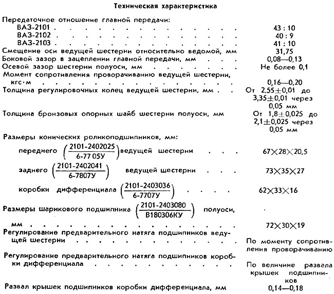
The main transmission gears are mounted in the reduction gear on tapered roller bearings with an adjusted preload to ensure their silent and durable operation. The required preload of bearings 27 and 34 of the drive gear 35 is ensured by tightening the self-locking nut 31 and the corresponding deformation of the spacer sleeve 26 installed between the inner bearing rings. Nut 31 is tightened with a torque of 12-26 kgf·m until the moment of resistance to turning over of the drive gear is equal to 0.16-0.20 kgf·m for new bearings or 0.04-0.06 kgf·m for bearings after a run of 30 km or more.
The correct position of the driving gear relative to the driven gear is ensured by selecting the thickness of the adjusting ring 24, placed between the supporting end of the driving gear and the inner ring of the rear bearing. The ring is selected to be of such a thickness that the gear is set to the nominal position.
To seal the main gear reducer housing, a rubber self-tightening seal 28 is pressed into the front neck of the reducer, which has a second protective edge in addition to the working edge. The seal operates on the ground cylindrical surface of the flange 30. To throw off oil from the seal, an oil deflector 32 is installed between the flange of the cardan shaft mount and the front bearing. On the outside, the seal is protected by a mud deflector 29 pressed onto the flange.
The driven gear 22 is secured to the differential case flange with eight self-locking bolts 41. Together with the differential case, the driven gear rotates in two tapered roller bearings 16 installed in the main gear housing. The seats of these bearings have covers, each of which is secured with two bolts 17 with spring washers. Detachable supports allow the differential to be removed from the gearbox housing together with the driven gear. The required position of the driven gear, i.e. the required value of the lateral clearance, is set with adjusting nuts 15. The same nuts are used to adjust the preliminary tension of the differential case bearings. The required preliminary tension is set if the camber of the bearing caps has reached the required value. In the required position, the adjusting nuts are locked with locking brackets 43, the projections of which enter the grooves of the adjusting nuts. The brackets are attached to the covers with 42 bolts and spring washers.
The differential is conical, with two satellites 21 mounted on a common axle 36. The satellites rest with their spherical ends on the spherical surface of the differential box.
Axle 36 is inserted into the differential box and is held from falling out by the driven gear of the main transmission, which covers the holes of the axle in the box. For better lubrication of the rotating satellites, spiral grooves are made on the axle.
Gears 23 of the axle shafts are centered in the cylindrical sockets of the box, and their ends rest on bronze washers 37. By selecting these washers according to thickness, the axial clearance of the axle shaft gears is adjusted.
The half-shafts 1 of the rear axle are forged from carbon steel together with flanges 13, to which the brake drums and wheels are attached by four bolts 2. The splined ends of the half-shafts enter the splined holes in the gears of the half-shafts.
Bearings 6 of the axle shafts are ball bearings, closed type with seals. On the axle shaft the bearing is secured with a locking ring 7, seated on the axle shaft in a hot condition. The outer ring of the bearing is installed in the socket of the flange 8 of the rear axle beam and secured with a plate 11, screwed to the flange 8 with four bolts.
Between plate 11 and flange 8 there is a stamped brake shield 12 with a rear brake mounted on it.
To seal the cavity of the rear axle, a rubber self-tightening seal 9 of the axle shaft is installed on the inside of the bearing 6 behind the locking ring 7. The oil deflector 4 and the grooves on the axle shaft serve to protect the brake pads from oil ingress in the event of its leakage outward due to damage to the bearing and oil seal seals.