
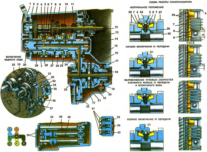
1. Back cover. 2. Gear box. 3. Drive gear IV gear. 4. Sliding clutch of the synchronizer of III and IV gears. 5. Retainer ball. 8. Retainer cracker. 7. The blocking ring of the synchronizer of II and IV transfers. 8. Drive gear III gear. 9. Driving gear of the 2nd gear. 10. Reverse drive gear. 11. Driving gear of the 1st gear. 12. Transmission input shaft. 13. Main gear drive gear. 14. Oil sump. 15. The axis of the satellites. 18. Satellite. 17. Half shaft gear. 18. Differential box. 19. Speedometer drive gear. 20. Driven gear of the speedometer drive. 21. Clutch housing. 22. Gear wheel of the main gear. 23. Adjusting ring. 24. Gear wheel 1st gear. 25. Sliding clutch for 1st, 2nd gears and reverse. 26. Gear wheel II gear. 27. Third gear gear. 28. The hub of the synchronizer coupling of III and IV gears. 29. Gear wheel IV gear. 30. The secondary shaft of the gearbox. 31. Intermediate reverse gear. 32. Axis of an intermediate gear wheel of a backing. 33. Reverse fork rod. 34. Rod retainer ball. 35. Detent spring. 36. Reversing light switch. 37. Reverse fork. 38. Crackers of the locking device. 39. Rod of the fork of inclusion of III and IV gears. 40. The rod of the fork of inclusion of I and II gears. 41. Stopper plugs. 42. Fork clutch synchronizer III and IV gears.
A - protrusion of the blocking ring a, b, c, d - gaps
The principle of operation of a mechanical gearbox is based on changing the value of the transmitted torque by replacing pairs of gears involved in the transmission of torque from the primary to the secondary shaft of the gearbox. A different combination of the number of teeth leading to the driven gears of each gear provides a change in the magnitude of the transmitted force (torque), and when reverse gear is engaged, the direction of force transmission.
The performance of the car, including its dynamics and speed, fuel consumption and cross-country ability, depend on the selection of the number of gears and gear ratios.
The forward gears of the gearbox are synchronized. This made it possible to ensure a smooth gear shifting process and increase the durability of the gearbox. Smooth gear shifting creates driving comfort, reduces driver fatigue and has a beneficial effect on traffic safety.
The principle of operation of the synchronizer is based on the alignment of the frequencies of rotation of the secondary shaft of the gearbox and the gear wheel of constant meshing of the required gear freely rotating on it.
The synchronizer operation diagram shows the sequence of its operation when the IV gear is turned on.
When the sliding clutch 4 is in the neutral position, the crackers 6 are in the center of the grooves of the hub 28 and do not act on the blocking ring 7 (see «The scheme of the synchronizer», scheme 1).
The start of turning on the IV gear is characterized by the fact that the sliding clutch, moving towards the gear 29., carries with it crackers 6., which abut against the protrusions A of the blocking ring, i.e., the gap c is selected. With further movement of the clutch, the crackers press the blocking ring against the conical surface of the synchronizer crown of the gear wheel 29. Under the action of friction forces between the conical surfaces of the blocking ring and the synchronizer crown and the inertia of the synchronized masses, the blocking ring rotates relative to the hub until the ring protrusions stop against the side walls of the hub grooves, i.e. That is, on the one hand, the gap in is selected, and on the other, it doubles and makes up the gap d. Due to the circumferential displacement of the locking ring by 1/4 step, the side bevels of the sliding sleeve 4 abut against the side bevels of the blocking ring 7, and further axial movement of the sliding sleeve is stopped. At the next moment, the alignment of the angular velocities of the gear wheel 29 of the IV gear and the secondary shaft 30 is completed. At this moment, the friction cones of the blocking ring and wheel 29 stop, as a result of which the force disappears. pressing the beveled surfaces of the teeth of the coupling and ring. This creates conditions for the full inclusion of IV gear, when the released clutch is easily connected to the crown of the blocking ring, and then to the synchronizer crown, connecting it to the hub. When the gear is fully engaged, the gaps between crackers 6 and protrusions A of the blocking ring 7 and the grooves of the hub are restored.
In the gearbox operation diagram, colored lines show the directions of torque transmission when each gear is engaged.
When the gear lever is in neutral, the engine is running and the clutch is engaged, the torque from the engine is transmitted through the clutch to the input shaft 12 of the gearbox. From the drive gears of the input shaft, the torque is transmitted to the gears of the same name of the secondary shaft, which, not having a direct connection with the shaft 30, will rotate freely on it. Torque is not transmitted to the main gear and differential.
When you turn on the 1st gear, the lever from the neutral position moves to the left, until resistance appears, and forward. The sliding clutch 25 of the synchronizer, moving towards the gear wheel 24, connects the synchronizer crown of the gear wheel 24 with the synchronizer hub, rigidly connected to the secondary shaft. The torque from the gear wheel 24 is transmitted through the clutch to the synchronizer hub and from it to the output shaft. Through the gear wheels 13 and 22 of the main gear, the torque is transmitted to the differential. The box 18 of the differential, rotating together with the axis 15 of the satellites, through the teeth of the satellites 16 and the gear wheels 17 of the axle shafts distributes the torque to the front wheel drives.
To turn on the second gear, the lever from the neutral position is moved to the left and back. In this case, the sliding clutch 25 connects the gear wheel 26 of the second gear with the synchronizer hub, and the torque from the wheel 26 through the sliding clutch 25 is transmitted to the synchronizer hub and to the output shaft.
Third and fourth gears are engaged by a different synchronizer by moving the lever forward or backward from the neutral position. When the third gear is turned on, the clutch 4 connects the wheel 27 to the synchronizer hub, and when the fourth gear is turned on, the wheel 29 connects to the hub of the same synchronizer. Torque is transmitted through the connected wheel and hub to the output shaft.
Reverse gear is engaged with the car completely stopped. When reverse is selected, the shift lever moves from neutral to the right to the stop with increased resistance and back. In this case, the reverse gear 31 connects the reverse drive gear 10 of the input shaft with the ring gear of the sliding clutch 25 of the synchronizer of I and II gears. Due to the intermediate gear, the torque transmitted to the secondary shaft changes its direction. Simultaneously with the reverse gear, the reversing lamp is turned on, since the fork 37 presses the reversing lamp switch rod 36 and the pump circuit is connected to the current source.
A clear separation of the lines of III-IV gears and reverse is achieved by a spring latch 15 (see ch. 20), which provides a sharp increase in the reverse gear selection force at the beginning and its fall at the end of the selection stroke
Gearbox parts are lubricated by spraying oil with gear rims of gears. To the needle bearings of the gears of the secondary shaft, oil is supplied from the oil chamber behind the front bearing of the secondary shaft through the oil sump 14. The oil level is measured with a ruler and should reach the upper mark.
To capture particles from the oil, there is a magnet installed at the bottom of the gearbox. The oil is drained from the crankcase through a hole closed with a plug 4 (see ch. 19).