
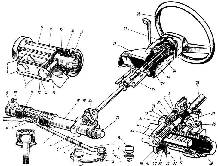
Pic. 101. Steering
The steering consists of a rack and pinion type steering mechanism and a steering gear. In crankcase tides 18 (pic. 101) steering gear on roller 29 (18) * and ballpoint 31 (19) bearings mounted drive gear 30 (4), which is engaged with rail 17 (3). The rail is pressed against the gear by a spring 40 through a ceramic-metal stop 39 (17), which is sealed in the crankcase with a rubber ring 37 (15). The spring rests on the nut 41 (16) with a retaining ring 38, which creates resistance to loosening the nut. The other end of the rail rests on the sleeve 16 (11) with two sealing rings 15. The gear ball bearing on the shaft is locked by ring 32, and is pressed against the crankcase seat by nut 35 (22) with o-ring 34 (21). The nut is locked in the crankcase with a washer and closed with anther 36 (23). mounted on the drive gear shaft. A protective washer 33 is installed between the locking 32 and sealing 34 rings. Marks A and B are made on the crankcase of the steering mechanism and on the anther for the correct assembly of the steering mechanism. A protective cap 28 is put on the steering gear housing on the left side (1), a pipe with a longitudinal groove is pressed on the right. Through the groove of the pipe and the holes of the protective cover 11 (12) bolts pass 7 (7) fastening rods 6 and 8 of the steering gear to the rack. Bolts pass through rubber-metal hinges 14 (9). pressed into the tie rod ends and the connecting plate 12 (8). The bolts are fixed with a locking plate 13.
* In parentheses are the corresponding positions in fig. 103.
The rack travel is limited in one direction by a ring (14), pressed onto the rail, and on the other side with a sleeve (6) carved metal hinge 14 thrust. In this case, both the ring and the sleeve abut against the steering gear housing.
The steering shaft is connected to the drive gear 30 (4) elastic coupling 20. The upper part of the shaft rests on a ball bearing 24. At the upper end of the shaft, the steering wheel 23 is fastened with a nut through the damping element 22.
The steering drive consists of two horizontal rods 6 and 8 and swivel arms 3 of the telescopic struts of the front suspension. The length of each rod is changed by a tubular rod 5, which is screwed onto the rod ends and locked with nuts 4. In the head of the rod tip 1, there are parts of the ball joint 2: an insert, a pin and a spring. Swivel arms,4 are welded to the front suspension struts.
Possible malfunctions of the steering, their causes and methods of elimination are given in table. 13.