




Contents: Checking functionality ↓ Full braking test ↓ Idle speed test ↓ Checking the traction relay ↓
If there are any doubts about the efficiency of the starter, it is necessary to check it on a test bench. The test bench must have a socket for installing the starter with a bushing for the front end of the anchor shaft. The electrical circuit for checking the starter on the test bench is shown in Figure 135. The connecting wires to the current source, ammeter and contact bolt of the starter traction relay must have a cross-section of at least 16 mm². The temperature during checks must be (25±5)°C, and the brushes must be well ground to the commutator.
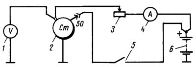
Figure 135. Connection diagram for testing the starter on the bench: 1 - voltmeter with a scale limit of at least 15 V; 2 - starter; 3 - rheostat 800 A; 4 - ammeter with 1000 A shunt; 5 - switch; 6 - battery
Checking functionality
When the current source voltage is 12 V, closing switch 5 (see figure 135), three starter activations are performed with different braking conditions. For example, with braking torques: 0.20-0.24; 0.55-0.66 and 0.90-1.08 kgf·m. The duration of each starter activation should be no more than 5 s, and the intervals between activations should be no less than 5 s.
If the starter does not rotate the stand's toothed ring or its operation is accompanied by abnormal noise, then disassemble the starter and check its parts.
Full braking test
The toothed ring of the stand is braked, the starter is turned on and the current, voltage and braking torque are measured, which should be no more than 500 A, no more than 7 V and no less than 1.4 kgf·m, respectively. The duration of the starter activation should be no more than 5 s.
If the braking torque is lower and the current is higher than the specified values, then the reason for this may be an interturn short circuit in the stator or armature winding or a short circuit of the windings to the housing.
When the braking torque and current consumption are lower than the values specified above, the reasons may be oxidation and contamination of the commutator, severe wear of the brushes or a decrease in the elasticity of their springs, hanging of the brushes in the brush holders, loosening of the stator winding terminals, oxidation or burning of the contact bolts of the traction relay.
When the pinion is fully braked, the starter anchor should not turn. If this happens, the freewheel clutch is faulty. To eliminate the fault, disassemble the starter and replace the damaged parts.
Idle speed test
The toothed ring of the stand is disengaged from the starter pinion. The starter is switched on and the consumed current and the rotation frequency of the anchor are measured, which should be no more than 60 A and 5000±500 rpm, respectively, with a voltage at the starter terminals of 11.5-12 V.
If the current strength and rotation frequency of the anchor differ from the specified values, then the reasons may be the same as in the previous test.
Checking the traction relay
Installed between the limiting ring 1 (see figure 133) and a 12.8 mm thick gasket with a gear and turn on the relay. The relay turn-on voltage when the gear rests on the gasket should be no more than 9 V at an ambient temperature of (20±5)°C. If the voltage is higher, this indicates a fault in the relay or drive.