
In case (pic. 133) four poles 17 are fixed with excitation windings, three of which are serial and one shunt. The body together with covers 6 and 14 is tightened with two bolts. The anchor has an end collector. The rear end of the armature shaft rotates in a ceramic-metal bushing pressed into cover 14, and the front end in a bushing pressed into the clutch housing.
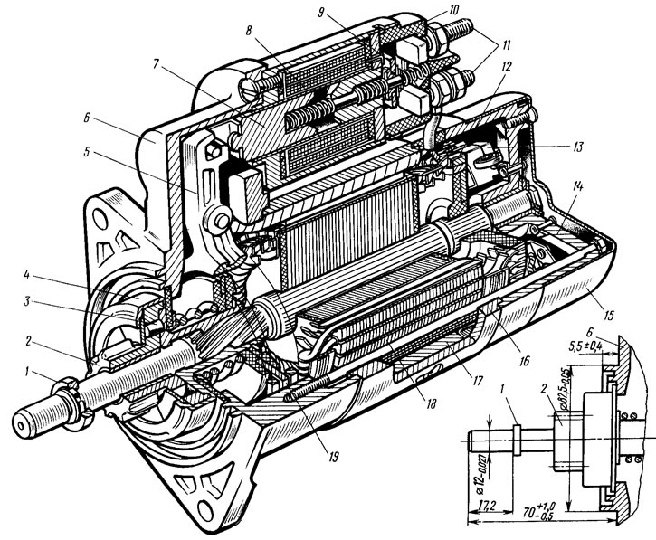
Pic. 133. Starter 29.3708: 1 - restrictive ring; 2 - drive gear: 3 - clutch roller; 4 - freewheel; 5 - drive lever; 6 - cover on the drive side; 7 - relay armature; 8 - relay winding; 9 - contact plate; 10 - relay cover; 11 - contact bolts; 12 - collector; 13 - brush; 14 - cover from the side of the collector; 15 casing; 16 - body; 17 - stator pole; 18 - anchor; 19 - driving ring
The starter connection diagram is shown in fig. 134. When the starter is turned on, the voltage from the battery through the auxiliary relay 6 type 113.3747-10 is supplied to both relay windings (retractor II and retainer I). After the relay contacts are closed, the retracting winding is turned off. (On the first batches of VAZ-2108 cars, relay 6 was not installed.)
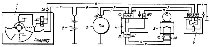
Pic. 134. Starter connection diagram: 1 - starter; 2 - battery; 3 - generator; 4 - mounting block (fragment); 5 - ignition switch; 6 - additional starter enable relay
Brief technical characteristics of the starter:
- Rated power, kW - 1.3
- Current consumption, A:
- at maximum power, no more than - 260
- in the inhibited state, no more than - 500
- idling, no more than - 60
Possible starter malfunctions, their causes and remedies are given in Table. 20.