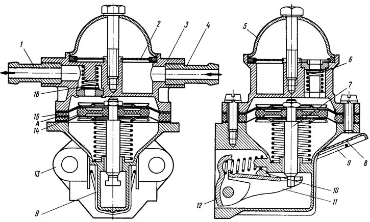
The fuel pump is of the diaphragm type, with a mechanical drive, equipped with a lever 8 (figure 14) manual pumping. The pump consists of a lower casing 13 with drive levers, an upper casing 3 with valves and pipes, a diaphragm unit and a cover 5. Three diaphragms are installed between casings 3 and 13: two upper working ones for fuel supply, the lower one is a safety diaphragm to prevent fuel from entering the drive casing if the working diaphragms are damaged. Between the diaphragms there are outer 15 and inner 14 spacer gaskets. The outer gasket has an opening A for fuel to exit if the working diaphragms are damaged. The diaphragms with plates are installed on the rod 7 and secured from above with a nut. On the rod under the diaphragm unit there is a compressed spring. The rod with an L-shaped tail is inserted into the slot of the balancer 11 and allows, without disassembling, to remove the diaphragm unit. Levers 12, 8 and balancer 11 are installed in the lower housing. Above the balancer there is a cam 10 of the lever 8 of manual pumping, pressed by spring 9. Inlet 6 and outlet 16 valves are installed in the upper housing 3. Cover 5 is attached to the pump housing from above with a central bolt. Between the cover and the housing there is a plastic mesh filter 2. The upper housing has a discharge 1 and suction 4 branch pipes.
Figure 14. Fuel pump
The VAZ-2108 fuel pump differs from the pump of previous models only in the location of pipes 1 and 4 in housing 3.