
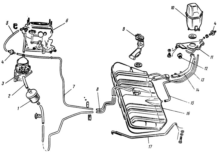
Pic. 13. Fuel tank and fuel lines: 1 - fuel fine filter; 2 - fuel supply hose to the fuel pump; 3 - fuel pump; 4 - check valves; 5 - fuel drain hose from the carburetor; 6 - carburetor; 7 - fuel drain pipe into the tank; 8 - tube for supplying fuel from the tank; 9 - fuel level sensor in the tank; 10 - separator; 11 - separator mounting bracket; 12 - fuel tank cap; 13 - separator hose; 14 - filling pipe; 15 - filling pipe hose; 16 - fuel tank; 17 - tank clamp
The fuel tank is stamped, welded and consists of two steel half-shells. The tank is connected by drain pipes to a non-separable separator 10 of gasoline vapors. To prevent leakage of fuel from the tank through the separator, it has a non-separable double-acting non-return valve on the outlet hose. The valve, as fuel is consumed from the tank, allows atmospheric air into the tank, and when the pressure in the tank rises, it releases fuel vapors from the tank.
The fine filter 1 is installed in front of the fuel pump on the hoses. The filter is of a non-separable design, with a paper filter element in a plastic case.
Air is supplied to the engine cylinders through a thermostat, air filter, carburetor and intake manifold.
Exhaust gases are released into the atmosphere through the exhaust manifold, exhaust pipe, additional and main mufflers.