
Before installing the pump, check the protrusion of the pusher. For proper installation of the pump, two of the three gaskets below are used: A - 0.27-0.33 mm; B - 0.70-0.80 mm; B - 1.10-1.30 mm. Installation is carried out in the following order. Install the heat-insulating spacer by placing gasket A under it (pic. 19), and a gasket B is placed on the plane in contact with the pump. Dimension d is measured (maximum protrusion of the pusher, set by slowly turning the crankshaft). If the size d is in the range of 0.8-1.3 mm, the pump is fixed; if the size d is less than 0.8 mm, then instead of the gasket B put the second gasket A; if dimension d is greater than 1.3 mm, then gasket B is replaced by gasket C. Dimension d is checked again and the pump is fixed to the engine. Gasket A must always be placed under the heat-insulating spacer. Gaskets A, B and C are interchangeable with the corresponding gaskets of previous car models.
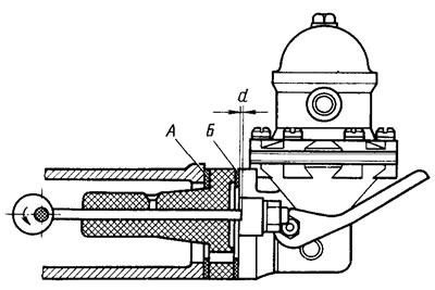
Pic. 19. Scheme for monitoring and adjusting the protrusion of the pusher of the fuel pump drive