




The main unit of the system is the electronic control unit 3 (figure 133). It receives information via two channels. Firstly, from the limit switch 2 of the carburetor about the position of the first throttle valve. This switch connects the output "5" of the control unit to the "ground" when the valve is closed. Secondly, from the ignition coil 1 about the crankshaft rotation speed. This information comes in the form of voltage pulses taken from the primary winding of the ignition coil. The control unit takes all this information into account and at specified moments produces voltage that turns on the electromagnetic valve of the carburetor.
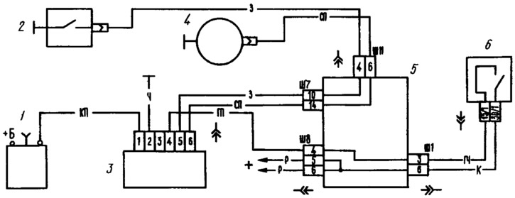
Figure 133. Wiring diagram of the carburetor electromagnetic valve control system:
1 - ignition coil; 2 - limit switch in the carburetor; 3 - control unit; 4 - electromagnetic valve; 5 - mounting block; 6 - ignition switch.
When the carburetor limit switch is not closed to "ground", i.e. the first throttle valve is not closed, the control unit supplies voltage to the solenoid valve at any speed of rotation of the crankshaft. If the limit switch is closed to "ground" (the damper is completely closed), then in this case the activation of the electromagnetic valve depends on the crankshaft speed. If at the moment of closing the first throttle valve the speed was higher than 2100 rpm, then the control unit will turn off the electromagnetic valve and turn it on only when the speed decreases to 1900 rpm.