
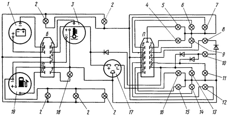
Pic. 132. Wiring diagram of the instrument cluster (back view):
1 - voltmeter; 2 - instrument lighting lamps; 3 - coolant temperature gauge; 4 - a control lamp of heating of back glass; 5 - control lamp high beam headlights; 6 - control lamp of the rear fog light; 7 - control lamp of side light; 8 - control lamp of direction indicators; 9 - reserve control lamp; 10 - control lamp «STOP»; 11 - oil pressure control lamp; 12 - alarm warning lamp; 13 - brake fluid level control lamp; 14 - control lamp of the air damper of the carburetor; 15 - control lamp of the battery discharge; 16 - control lamp of the parking brake system; 17 - socket for the relay-breaker of the control lamp of the parking brake system; 18 - control lamp of the fuel reserve; 19 - fuel gauge.
In the connecting blocks, the numbers indicate the conditional numbers of the plugs.
Instrument clusters can be domestically produced or manufactured in Hungary. They are slightly different in design, but have the same arrangement of devices and the same connecting dimensions.
The instrument cluster includes a speedometer, fuel gauge, coolant temperature gauge, voltmeter, econometer and 12 warning lights.
Speedometer
The speedometer consists of a pointer indicator of the speed of the car and two counters: summing and daily distance traveled. The readings of the last counter can be reset with a handle placed on the instrument panel or located directly on the instrument cluster. You can reset the meter readings only when the car is stationary. The speedometer drive shaft is driven by a flexible shaft from a drive mounted on the clutch housing. The principle of operation of the speed indicator is induction. A permanent magnet is installed on the drive shaft of the speedometer, which, when rotated, induces eddy currents in a metal disk located on the same axis as the arrow. These currents create their own magnetic field, which interacts with the magnetic field of the permanent magnet. As a result, a moment is created that turns the disk and the arrow at a certain angle, depending on the frequency of rotation of the input shaft.
The counters are driven by a drive shaft through three worm gears giving a deceleration of 1:1000. The summing counter has six counting drums, and the daily counter has four. The drums have internal gears with intermediate wheels. The number of teeth is chosen so that the gear ratio between adjacent drums is 1:10.
Fuel gauge
Fuel level indicator - magnetoelectric type. In it, a permanent magnet, fixed on the same axis with an arrow, interacts with a magnetic field created by two coils located mutually perpendicular. A sensor is included in the electrical circuit of the coils, which changes its electrical resistance depending on the fuel level. In this regard, the strength of the currents in the windings of the pointer coils and the direction of the magnetic flux created by them change. Under the influence of this magnetic flux, the permanent magnet connected to the pointer rotates and moves the pointer pointer.
The pointer sensor is installed in the fuel tank. It has a wire-wound resistor over which a float-controlled contact slides. Depending on the fuel level, the float rises or falls and moves the movable contact of the resistor, changing the resistance of the sensor. The sensor also has contacts to turn on the fuel reserve warning lamp installed in the gauge. These contacts close when 4...6.5 liters of fuel remain in the tank.
Coolant temperature gauge
The coolant temperature gauge is designed and operates in the same way as the fuel level gauge, but has different coil winding data. It works in conjunction with a sensor mounted on the engine's cylinder head. The sensor has a thermistor that changes its electrical resistance depending on temperature.
Voltmeter
The voltmeter is also of the magnetoelectric type and the principle of its operation is similar to the principle of the above devices. With the ignition on and the engine off, the voltmeter shows the voltage at the battery terminals, and with the engine running, the voltage generated by the generator. If, with the engine running, the arrow is in the red zone at the beginning of the scale (8...10 V), then this indicates a discharge of the battery due to the weak tension of the alternator drive belt or the alternator itself. The red zone at the end of the scale corresponds to 15... 16 V. If the arrow is in this zone, then the generator voltage regulator is faulty. Intermediate pointer position (between red zones) indicates the normal operation of the generator.
Econometer
The econometer is a vacuum gauge that measures the vacuum in the engine intake manifold. The vacuum value has a direct and inverse relationship with fuel consumption. The less the throttle in the carburetor is ajar, the greater the vacuum in the intake manifold, and the fuel consumption is less. At high engine loads, the throttle valves open more, the vacuum drops (econometer needle is in the yellow zone), and fuel consumption increases. Thus, the econometer helps the driver to maintain the most economical driving mode by selecting the gear in the gearbox and the crankshaft speed.
The econometer is a mechanical device. It has a thin sealed tube. Under the action of rarefaction, it is deformed and turns the arrow through the lever mechanism.