
Cylinder head
Cast from aluminum alloy and has wedge-shaped combustion chambers (pic. 12, a). Each chamber has a threaded hole for a spark plug. On the left side in the front and rear of the cylinder head 2 there are channels for draining oil into the oil sump.
7 valve seats made of special cast iron are pressed into the cylinder head to provide high strength when exposed to shock loads. The working chamfers of the seats are machined after pressing in assembly with the cylinder head to ensure the exact alignment of the chamfers with the holes of the 3 valve guide bushings.
The valve guides are also made of cast iron and are pressed into the cylinder head with an interference fit. On the outer surface of the guide bushings there is a groove where the retaining ring 8 is inserted. It ensures the accuracy of the position of the bushings when they are pressed into the cylinder head and protects them from possible falling out.
The bores in the bushings are machined after the bushings are pressed into the cylinder head to ensure the accuracy of the diameter and location in relation to the seat and valve facets. The bores of the guide bushings have spiral grooves for lubrication. The inlet valve bushings are grooved up to half the length of the hole, and the exhaust valve bushings are grooved along the entire length of the hole.
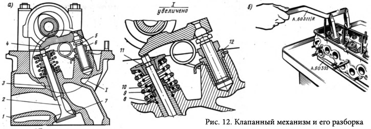
Oil deflector caps 9 made of heat-oil-resistant rubber with a steel reinforcing ring 10 are put on top of the guide bushings. The caps cover the valve stem and serve to reduce the penetration of oil into the combustion chamber through the gaps between the guide bushing and the valve stem.
Until 1974, cylinder heads 2101-1003015 were installed on 2101 engines, providing a compression ratio of 8.8. Since 1974, the volume of the combustion chambers has been increased in these heads and, as a result, the compression ratio has dropped to 8.5. The engine began to work softer, its durability increased, and its power characteristics remained almost the same.
On the first batches of engines 21011 (in 1974) cylinder heads 21011-1003015 were installed, which, in combination with pistons 21011-1004014, which had a flat bottom, provided a compression ratio of 8.8. Cylinder head 21011-1003015 had the same volume (but different sizes) combustion chambers, as in the head 2101-1003015, modified for a compression ratio of 8.5, and reduced ducts for the passage of coolant from the block to the cylinder head.
From 1975 to the present, a unified cylinder head 21011-1003015-10 has been installed on all VAZ engine models. It has both the dimensions and volume of the combustion chamber, like the cylinder head 2101-1003015, modified for a compression ratio of 8.5, and the coolant ducts, like the head 21011-1003015.
At the same time, in 1975, the compression ratio of the 21011 engines was reduced to 8.5 by installing pistons 21011-1004014-10 with a recess on the bottom with a diameter of 55 mm and a depth of 1.9 mm.
Valve mechanism
Valves 2 (see fig. 12) are driven by a camshaft through steel levers, an adjusting bolt 5. The bolt is kept from self-unscrewing by a lock nut 6.
The valve has two cylindrical springs: external and internal, based on two support washers. The upper support plate of the springs is held on the valve stem by two biscuits 11, which, when folded, have the shape of a truncated cone.
The inlet valve is made of chromium-nickel-molybdenum steel. The exhaust valve operates at high temperatures in an aggressive exhaust gas environment. Therefore, it is made weldable in two parts. The valve stem is made of chromium-nickel-molybdenum steel, which has good wear resistance and thermal conductivity for efficient heat dissipation from the valve disc to the valve guide. The valve disc is made of heat-resistant chromium-nickel-manganese steel. In addition, to reduce the wear of the valve face, a special heat-resistant alloy is welded onto it.
To increase the wear resistance of the rods, both valves are nitrided, and the ends of the rods, on which the levers rest, are hardened by high-frequency currents.