
Install the cylinder head on board A.60335.
Disconnect the exhaust manifold and intake manifold with carburetor (at the same time the hot air intake is removed).
Disconnect the cooling jacket outlet
Disconnect the fluid outlet pipe to the heater.
Remove levers 11 (pic. 2-41) valves, freeing them from the springs 12. Remove the lever springs.
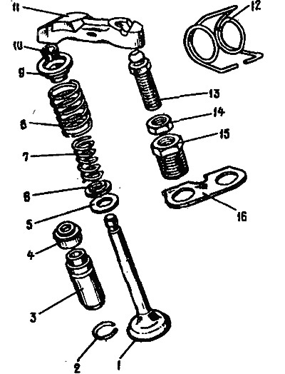
Pic. 2-41. Valve mechanism details: 1 - valve; 2 - retaining ring; 3 - guide sleeve; 4- oil cap; 5 - support washer of the outer spring; 6 - support washer of the internal spring; 7 - inner spring 8 - outer spring; 9 - a plate of spring, 10 - crackers; 11 - valve drive lever; 12 - lever spring, 13 - adjusting bolt; 14 - adjusting bolt locknut; 15 - bushing of the adjusting bolt, 16 - locking plate of the lever spring
Loosen the locknuts 14, unscrew the adjusting bolts 13 and the bushings 15 of the adjusting bolts.
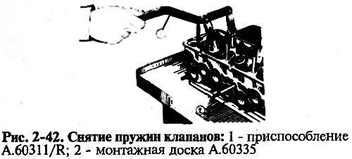
Install tool A.60311/R as shown in fig. 2-42, compress the valve springs and loosen the cotters. Instead of the portable tool A.60311/R, the fixed tool 02.7823.9505 can also be used.
Remove valve springs with plates and support washers. Turn the cylinder head and remove the valves from the underside.
Remove the oil seals from the guide bushings.
Assemble the cylinder head in reverse order.
Cleaning the cylinder head
Install the head on the stand A.60353.
Remove carbon deposits from the combustion chambers and from the surface of the exhaust channels with a metal brush driven by an electric drill. Clean and inspect the inlet passages and oil supply passages to the valve actuating levers.