




This chapter describes the clutch drive with a servo mechanism and the features of the design of a backlash-free drive, which is simpler and more reliable.
Clutch drive - mechanical, cable, with servo spring 24 (figure 58), which reduces the force applied to the clutch pedal when it is released and ensures a clear return of the clutch pedal to its original position, i.e. it acts as a release spring.
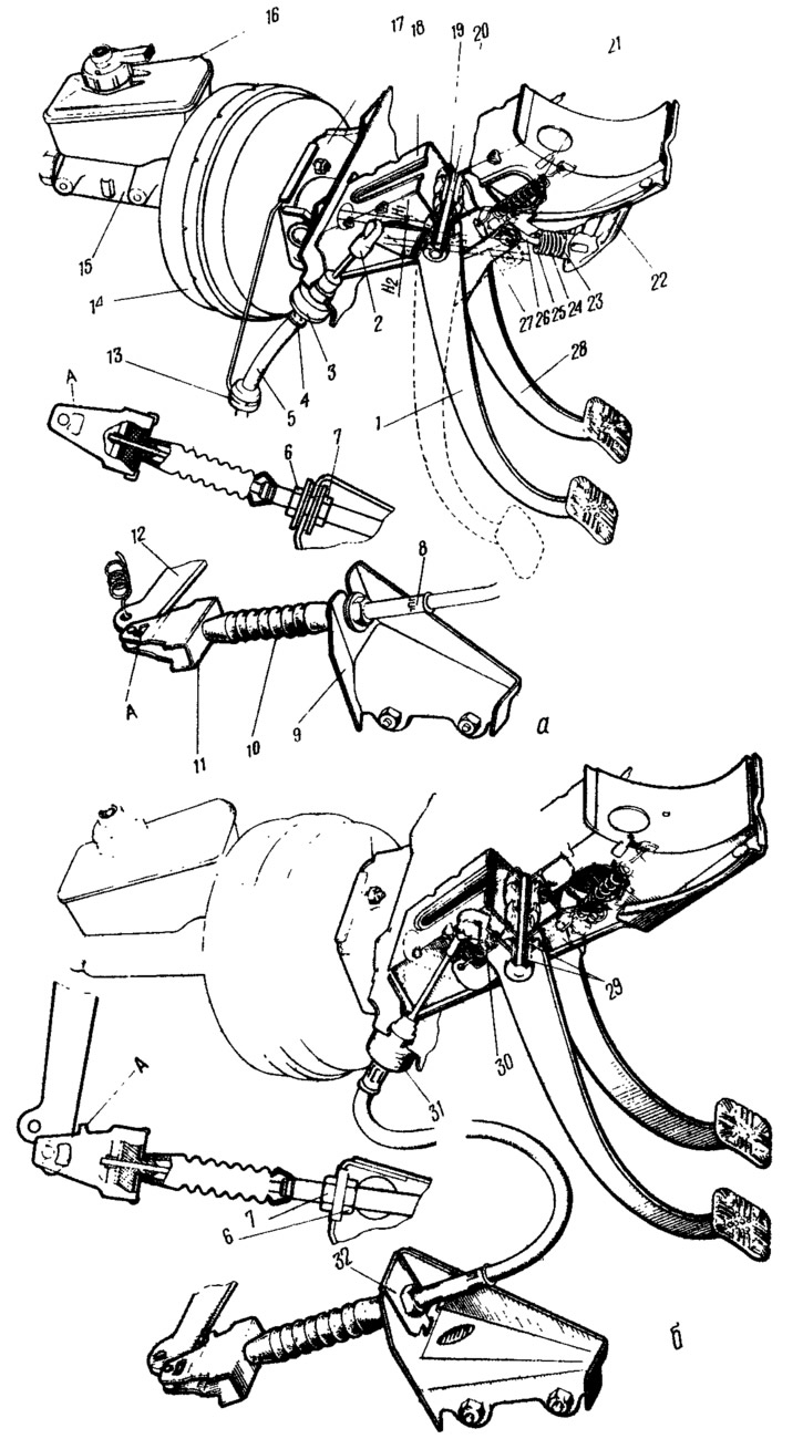
Figure 58. Clutch release drive:
a) with servo mechanism; b) gapless type; 1 - clutch pedal; 2 - pedal earring; 3 - rubber buffer; 4 - upper end of the cable sheath; 5 - cable sheath; 6, 7 - adjusting nuts; 8 - lower end of the cable sheath; 9 - bracket for fastening the lower end of the cable sheath; 10 - protective cover; 11 - cable leash; 12 - clutch release fork lever; 13 - sleeve of the draw hook; 14 - vacuum booster; 15 - master cylinder; 16 - tank; 17 - vacuum booster mounting bracket; 18 - clutch and brake pedal bracket; 19 - locking bracket; 20 - pedal axle; 21 - brake pedal release spring; 22 - servo mechanism bracket; 23 - servo spring support; 24 - servo spring; 25 - servo pusher thrust washer; 26 - pusher; 27 - spacer sleeve; 28 - brake pedal; 29 - Clutch pedal bushings; 30 - clutch pedal release spring; 31 - clip; 32 - fixing plate; A - mustache.
The clutch and brake pedals are suspended on the axle 20 to the bracket 18, which is welded to the front body shield and to the air intake box. Two plastic bushings are installed in the pedal hubs. A plastic spacer bushing 27 is installed between the brake pedal and the bracket cheek on the axle. The clutch pedal is located on the axle between the bracket cheek and the thrust washer placed under the pedal axle head. The axle is held in the bracket by a locking clamp 19.
A servo lever is welded to the clutch pedal, which is pivotally connected to the pusher 26. At the end of the pusher, a pre-compressed spring 24 is installed between the thrust washer 25 and the support 23. The support 23 rests with its projection against the socket of the bracket welded to the bracket of the clutch and brake pedals. The lower end of the pusher 26 freely passes through the opening of the support and bracket.
The information is posted on the portal: VazBook.ru
The upper part of the clutch pedal is connected to the plastic earring 2 of the clutch drive cable. The cable is located in a casing, at both ends of which tips are fixed. The lower tip 8 is clamped in the socket of the bracket 9 by two nuts 6 and 7 with washers and rubber bushings. A leash 11 is fastened to the lower end of the cable, which is connected with a finger to the clutch release fork lever. The end of the cable coming out of the casing is protected by a rubber cover 10. The upper tip 4 of the cable casing is located in a rubber buffer 3, whose end rests against the socket of the front of the body. The flange of the tip rests through the washer against the end of the buffer, which prevents the cable casing from moving. A pull hook with a bushing 13 is used to support the upper branch of the cable.
Rubber parts in the clutch drive dampen vibrations of parts, reduce vehicle noise and at the same time ensure the elasticity of the clutch drive. Therefore, it is sometimes difficult to detect the end of its free travel by the force on the clutch pedal. As a result, the free travel is checked and adjusted on the clutch release fork lever.
The backlash-free clutch drive has the following design features: (figure 58, b):
- the drive does not have a servo mechanism, so the clutch pedal does not have a servo lever, and the clutch and brake pedal bracket does not have a bracket with a socket for the servo support;
- the clutch pedal is connected to the end of the cable with a finger and is pulled to the extreme forward position by the release spring 30, as a result of which the clutch release bearing is pressed with a force of 5...7 kgf to the petals of the pressure spring. Such a force does not cause the pressure spring to deflect on the support rings, i.e., the clutch does not slip;
- in the gearbox bracket, at the point where the cable is attached, rubber bushings and support washers are not installed, and to prevent the cable from coming out of the bracket socket 9, a fixing plate 32 is used;
- there is no release spring at the lever 12 of the clutch release fork;
- the cable leash has a stop tab A to prevent the cable leash from separating from the clutch release fork lever;
- rubber buffer 3 is located in a steel cage, which limits its deformation, and therefore the travel of the clutch pedal;
- it is not the free travel of the clutch release fork lever that is adjusted, but the full travel of the clutch pedal.