
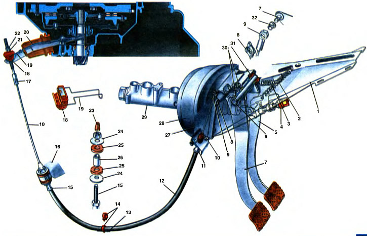
1. Bracket for clutch and brake pedals. 2. Brake pedal release spring. 3. Clutch pedal return spring. 4. Stoplight switch. 5. Brake pedal. 6. Axis of pedals. 7. Clutch pedal. 8. Locking bracket. 9. Upper cable end. 10. Rope. 11. Upper tip of the cable sheath. 12. Rope sheath. 13. Mudguard body. 14. Cable fastening bracket. 15. Lower tip of the cable sheath. 16. Gearbox cover. 17. Lower tip of the cable. 18. Leash. 19. Leash holder. 20. Clutch release fork. 21. Adjusting nut. 22. Locknut. 23. Protective cap. 24. Washer. 25. Rubber bushing. 26. Spacer sleeve. 27. Body front guard. 28. Vacuum amplifier. 29. The main cylinder of the brake drive. 30. Clutch pedal bushing. 31. Spacer sleeve. 32. Cable tip bushing.
The clutch is released through a mechanical drive, in which there is no gap between the clutch release bearing and the pressure spring petals, i.e. the clutch pedal does not have a free code. There is also no fixed position of the pedal, since there is no stop limiting the movement of the pedal up. The main parameter that determines the normal operation of the clutch drive is the working stroke of the pedal, which should be equal to 105... 115 mm. When the lining of the clutch disc is worn, the pedal travel increases, and at a certain moment (with a stroke of 140 mm and above) it becomes necessary to adjust the clutch drive.
The clutch drive is cable, consists of a pedal 7, a cable 10 assembly and a fork 20 acting on the clutch release bearing clutch.
The clutch pedal is suspended on the axis 6 common with the brake pedal 5 in the bracket 1. The bracket for the clutch and brake pedals is attached to the shield 27 of the front end of the body. A vacuum booster 28 is attached to the bracket plate from the side of the engine compartment, complete with the main cylinder 29 of the brake drive. From below, to the pedal bracket, in the passenger compartment, the steering column shaft bracket is attached at four points.
The clutch pedal 7 with the hub is clamped between the cheek of the bracket and the washer of the axle 6 of the pedals. Split plastic bushings 30 are installed in the pedal hub, which are lubricated during assembly with Litop-24 grease. During operation of the car, the bushings do not need additional lubrication. The brake pedal is mounted on the axle between the cheek of the bracket and the spacer plastic sleeve 31. The axis of the pedals in the bracket is fixed with a locking clip.
The upper tip 9 of the cable is connected through a plastic sleeve 32 to the clutch pedal finger and is fixed with a locking bracket 8, and the lower tip 17 of the cable is connected through the leash 18 to the clutch release fork 20. The leash, with possible movements of the tip of the cable, is held on the fork using a wire retainer 19. The route of the cable in the engine compartment is determined by its sheath 12, the upper tip 11, which is fixed through the seal on the front end of the body, and the lower tip 15 of the shell is installed in the nest of the tide cover 16 of the box gears together with damping 25 and spacer 26 bushings and secured through thrust washers 24 with a nut. To protect the inner cavity of the shell from contamination, the tips are equipped with protective caps 23. Additionally, the cable shell is fixed on the mudguard 13 of the body with a plastic bracket 14.
Bearing 12 (see ch. 17) clutch release ball, self-adjusting, with protective washers. It is installed with a small radial clearance on the coupling 13 and in the seat of the metal flange 19. The bearing is pressed against the flange by a wavy spring washer, into the slot of which the coupling antennae enter, which are then bent. This connection makes it possible «swim», i.e. self-align the bearing on the coupling, which increases the durability of the contact pair: the bearing and the pressure spring. The inner race of the bearing is wider than the outer one, it is constantly pressed against the petals of the pressure spring and rotates from this contact together with the leading part of the clutch. The clutch 13 of the clutch release bearing is located on the guide sleeve 20, which is attached to the clutch housing with its flange. The clutch release fork 14 is stamped from steel and has a box section. A hemispherical socket is stamped in the fork, with which it rests on the ball bearing 16. The fork is pressed against its support by a wire spring 15 fixed on the fork. The inner end of the fork enters the groove of the flange of the clutch release bearing, and the outer end is connected through a leash to the cable.
Despite the constant preload of the bearing to the petals of the pressure spring, its performance is maintained for the entire run until the overhaul. This is ensured by improved bearing sealing and the absence of dynamic loads on the bearing when the clutch is released. The latter is typical in drives where there is a gap between the bearing and the pressure spring petals, when at the moment the clutch is released, the bearing perceives sharply increasing loads
Clutch work
Clutch of permanently closed type. i.e. constantly on In this position, the driven disk 4 (see ch. 17) under the force of the pressure spring 7 is clamped between the surfaces of the flywheel 2 and the pressure plate 6. Due to the friction forces between the surfaces of the discs, the torque from the flywheel and the pressure plate is transmitted to the driven disc and through the damper parts to the hub 24 of the driven disc and to the input shaft 22 of the gearbox. Thus, when the engine is running and the clutch pedal is released, the parts of the driving and driven parts of the clutch rotate as one. And if a gear is engaged in the gearbox, the torque from the engine will be transmitted to the driving wheels of the car.
To disengage the clutch, the driver presses the pedal 7 (see ch. 18) clutch. Turning on the axis 6, it pulls the cable 10 with its upper shoulder through the finger and at the same time stretches the retracting spring 3. Moving in the shell, the cable turns the plug 14 on the ball bearing (see ch. 17) disengaging the clutch. The inner arm of the fork moves the clutch 13 with the clutch release bearing 12 along the guide sleeve towards the flywheel. The pressing force on the petals of the pressure spring increases, and the spring 7, bending on the support rings 8, stops pressing on the pressure disk 6. The driven disk 4 is released, the friction forces between the disks disappear, and the torque is no longer transmitted to the transmission units. At this point, bumpless gear shifting is possible, after which the driver gently releases the clutch pedal in order to prevent a sharp increase in the load on the transmission parts. This prevents premature wear, especially clutch discs and gears.
When the pedal is released, it returns to its original position under the action of a return spring. Together with it, the fork with the clutch of the clutch release bearing is in its original position. The pressure spring, assuming its original shape, moves the pressure plate towards the flywheel. When you gently press the driven disk, its wavy surface gradually becomes flat, allowing the disk to first slip, as a result of which the clutch engages smoothly. In this case, the torque from the flywheel 2 is transmitted to the clutch cover 5 and the pressure plate 6 and due to friction forces to the driven disc 4, then from it through the damper parts to the hub 24 of the driven disc and through the spline connection to the input shaft 22 of the gearbox.
The torsional vibrations of the engine crankshaft are absorbed by the damper friction element and its six springs. When the torque value changes, the driven disk 4, together with the damper plates 26 and 34, move relative to the hub 24. In this case, friction occurs between the surfaces of the hub, friction ring 31 and support ring 33, and the damper springs 25 are compressed, absorbing torsional vibrations. Therefore, the variable torque will be transferred to the disc hub more smoothly and the load on the spline connection of the hub and the input shaft will also be smoothly transferred. The compression stroke of the damper springs depends on the amount of transmitted torque. The rotation of the driven disk with the damper plates relative to the hub is limited by the stop of the rivets 30 in the horseshoe cutouts of the hub, after which the compression of the springs stops.
Due to the wear of the clutch discs, the pedal travel gradually increases, i.e. the pedal rises, since its rise is not limited by anything. This changes the levels of the clutch and brake pedals. This makes pedaling difficult. Therefore, when the clutch pedal travel is 115 mm or more, it should be adjusted with nut 21 (see ch. 18), the position of which is fixed with a lock nut 22. The adjustment procedure is as follows:
- loosening the lock nut 22, by rotating the adjusting nut 21 set the clutch pedal stroke equal to 105... 115 mm;
- press the clutch pedal all the way to the floor mat at least three times and check the amount of pedal travel;
- if necessary, adjust the pedal travel with nut 21;
- without changing the position of the pedal, tighten the locknut 22 with a torque of 1.5... 2.0 kgf·m.