
The gap is measured with a feeler gauge on a cold engine (at +20°C) between the camshaft cam (the cam must be pointing up from the pusher) and adjusting washer of the valve lifter.
The nominal clearance for the intake valve is (0,2±0,05) mm, for graduation - (0,35±0,05) mm. The gaps are adjusted by selecting the thickness of the shims. Spare parts are supplied with washers with a thickness of 3 to 4.5 mm through 0.05 mm.
Counting from the camshaft drive belt, the 1, 4, 5 and 8th exhaust valves, 2, 3, 6 and 7th are intake valves.
The order in which the gaps are adjusted does not matter.
You will need: a device for adjusting the clearances in the valve drive, a set of probes for checking the clearances, shims.
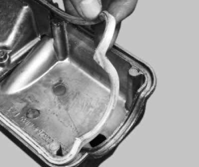
1. Remove the cylinder head cover (see «Replacing the Head Cover Gasket»).
2. Set the piston of the first cylinder to the TDC of the compression stroke. To do this, turn the crankshaft so that the mark on the camshaft pulley matches the mark (tendril) on the rear cover of the camshaft drive. Then turn the crankshaft another 40-50°- the camshaft cams will turn away from the pushers.
Warning! Turn the crankshaft only by the bolt securing the pulley to it (it is forbidden to turn the crankshaft by the camshaft pulley).
Helpful Hints: It is inconvenient to turn the crankshaft by the pulley mounting bolt, therefore, to set the camshaft cams to the upper position, turn on any gear (better IV) and slowly roll the car until the cams are in the desired position. If it is not possible to move the car, hang out any front wheel and, turning on any gear, set the cams by turning the posted wheel.
3. Use a set of feeler gauges to measure the clearances in the drive of those valves whose cams are directed upwards from the pushers (in this case, these are the 4th, 6th, 7th and 8th valves). It is necessary to replace the adjusting washers of those valves, the gaps in which differ from the nominal. Record the measured clearances.
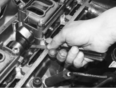
4. To make it easier to remove the adjusting washer, two grooves are made in the pusher. Use a screwdriver to turn the pusher by the groove so that it is convenient to pry the washer. For ease of operation, remove the oil from the top of the block head (around pushers).
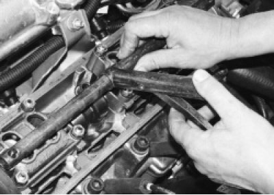
5. Install the valve spring compressor on the head cover mounting studs.
6. Put the washers on the studs, turning them over so as not to jam the flanging on them, and tighten the cap nuts.
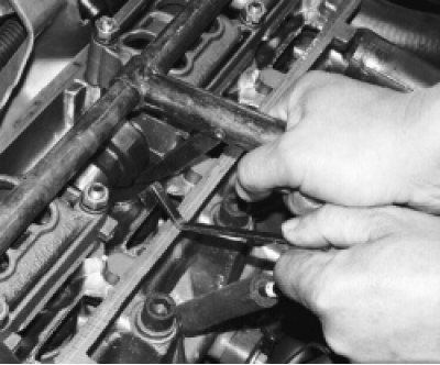
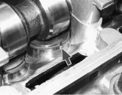
7. Pressing the tool lever down, sink the pusher on which the adjusting washer is being replaced, and insert the retainer under the camshaft so that..
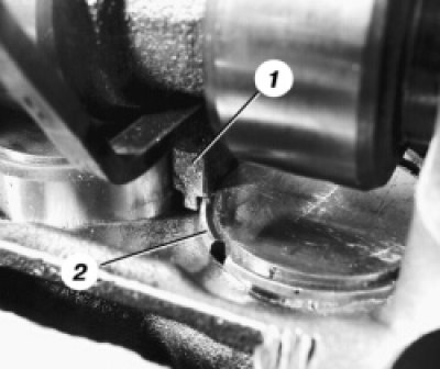
8.... the protrusion on the latch 1 fixed the pusher 2 in the recessed position.
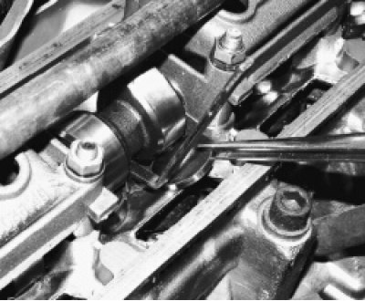
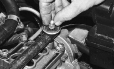
9. Pry off the adjusting washer with a screwdriver and, using, for example, tweezers, remove the washer from the pusher.
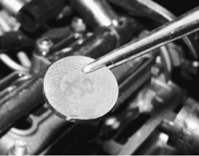
10. Write down the thickness of the shim - it is marked on one of its sides. If the inscription is not visible, measure the thickness of the washer with a micrometer.
11. Calculate the thickness of the new shim using the formula (all values in mm) H = B+A-C, where
A is the value of the measured clearance;
B is the thickness of the old washer;
C - nominal clearance;
H is the thickness of the new washer.
For example (for intake valve):
A=0.26 mm, B=3.75 mm, C=0.2 mm, then H=3.75+0.26-0.2=3.81 mm.
Within clearance tolerance (±0.05 mm) we select the closest washer in thickness 3.8 mm.
12. Install a new washer in the pusher with the thickness calculated according to the formula with the inscription down (to the pusher). Drown the pusher with a tool and remove the retainer.
13. Check the clearance with a feeler gauge. If it differs from the nominal, repeat the adjustment.
14. Rotate the crankshaft one turn (360°) and adjust the clearances in the drive of the 1st, 2nd, 3rd and 5th valves in the same order. Then pour oil into the top of the block head if it was removed.
15. Check up a condition of a lining of a cover of a head of the block, if necessary replace it.
16. Install the removed parts in the reverse order of removal.