




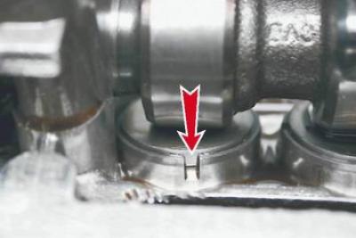
Note. To compensate for thermal expansion of the valve stem, a gap is required between the camshaft cam and the valve tappet. For intake valves, the gap should be 0.15-0.25 mm, and for exhaust valves - 0.30-0.40 mm. The gap is set by selecting the thickness of the adjusting washers. The washers are installed in a niche located on the tappets at the top. To make it easier to remove the washers, grooves are made on the upper edges of the tappets.
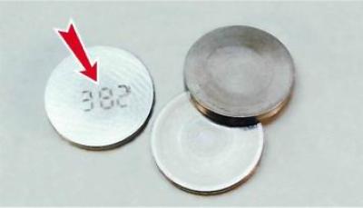
The size of the washer is marked on its non-working surface.
Advice.It is more convenient to divide the work into two stages. First, measure the gaps and calculate the thickness of the new washers, and only then purchase and install new washers.
To complete the work you will need:
- set of flat feeler gauges;
- clearance adjusting device;
- micrometer (with a measurement range of 0-25 mm);
- tweezers.
Warning! Checking and adjusting clearances is only performed on a cold engine (at a temperature of about +20°C).
Sequence of execution
1. Prepare the car for work (see "Preparing the car for maintenance and repair").
2. Remove the cylinder head cover (see "Cylinder head cover for engines 2111 and 21114 (8v) - removal and installation, gasket replacement").
3. Remove the front timing belt cover (see "Timing Belt - Replacement").
4. Using a medical syringe or rubber bulb, remove any remaining oil around the valve lifters.
5. Install the valve adjustment device on the cylinder head studs and secure it with the nuts that secured the cylinder head cover.
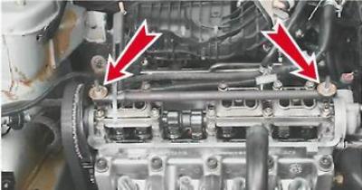
Recommendation. There are several ways to adjust the clearances. They differ in the order of measuring the clearances at the valves. In any case, the clearances are checked only with the valves closed (their tappets are not pressed by the camshaft cams). If it is difficult to determine the position of the valves, follow the method below.
6. Rotating the crankshaft clockwise, we set the piston of the first cylinder to the TDC position of the compression stroke.
Note: The crankshaft can be rotated with a spanner by 17 mm (or on 19 mm) by the bolt that secures its pulley or by the teeth of the flywheel with a large slotted screwdriver. To do this, remove the rubber plug from the hole in the clutch housing.
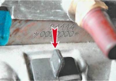
7. Turn the shaft from the TDC position to an angle of 40-50° (for 3 teeth of camshaft pulley), using feeler gauges of appropriate thickness, we determine the clearances in the drive of the 1st and 3rd valves (when counting in order from the camshaft pulley).
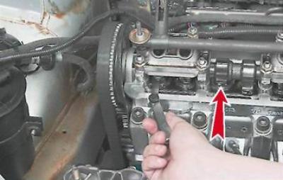
Note: The nominal thickness feeler gauge should be slightly pinched in the gap between the camshaft cam and the tappet adjusting washer.
8. If the gap is not within the norm, turn the pusher with the groove towards you. Use the device to push the valve down, holding the pusher from turning with a screwdriver inserted into the groove. Use the device's lock to stop the pusher in the lower position.
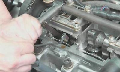
9. Use tweezers to remove the adjusting washer.
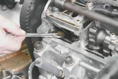
10. Using the markings on the washer, we determine its thickness. If the inscription has worn off, we measure the thickness of the washer with a micrometer.
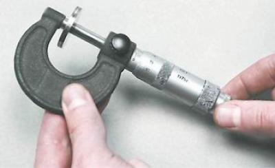
11. Calculate the clearance of the new adjusting washer using the formula:
a) for inlet valves Z = Y + X - 0.2 mm;
b) for exhaust valves Z = Y + X - 0.3 mm;
where Z is the calculated thickness of the new adjusting washer, Y is the thickness of the removed washer; X - gap determined by feeler gauge.
12. We select a new washer whose thickness is close to the calculated one (+0.05 mm).
13. Install a new washer into the pusher (marking down).
14. Press the pusher with the device and remove the retainer.
15. Following the sequence specified in Table 8.1, check and adjust the clearances in the drive of the other valves.
16. After removing the valve adjustment tool, install the removed parts in the reverse order of disassembly.
Table 8.1
|
The angle of rotation of the crankshaft from the TDC position of the compression stroke of the first cylinder, deg. |
Cam |
|
|
Outlet |
Inlet |
|
|
40-50 |
1 |
3 |
|
220-300 |
5 |
2 |
|
400-410 |
8 |
6 |
|
580-590 |
4 |
7 |