
The gap is adjusted in the following order. Remove the spare wheel, air filter and cylinder head cover by disconnecting the crankcase ventilation hoses from the carrier. Remove the front protective cover of the toothed belt, check and, if necessary, adjust the tension of the camshaft drive belt.
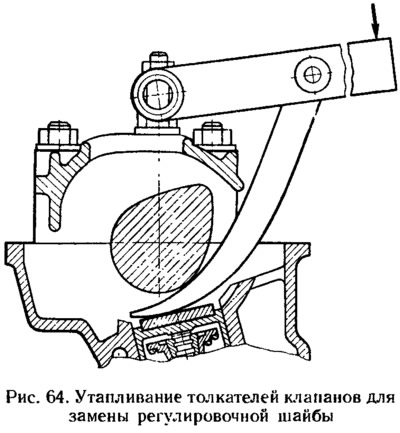
The spark plugs are removed and the oil is removed from the oil baths in the cylinder head. Inspect the surface of the camshaft cams: they should not have scuffs, shells, wear and deep scratches. Install tool 67.7800.9510 on the studs of the cylinder head cover (pic. 64).
Turn the crankshaft until the alignment marks on the pulley and the back cover of the toothed belt are aligned (see fig. 7), and then turn it 40-50° (2.5-3 teeth on the camshaft pulley). In this case, there will be a combustion phase in the first cylinder. The crankshaft should only be rotated clockwise, either by the bolt securing the alternator drive pulley, or using tool 67.7811.9513, by the camshaft pulley. It is not allowed to turn the crankshaft by the camshaft pulley bolt, as the bolt may be damaged.
Check the gaps at the first camshaft cam with a set of feeler gauges. If the gap differs from the norm, then with tool 67.7800. 9510 (see fig. 64) sink the valve tappet and fix it in the lower position by installing a retainer 2 between the tappet edge and the camshaft (pic. 65) 67.7800.9504.
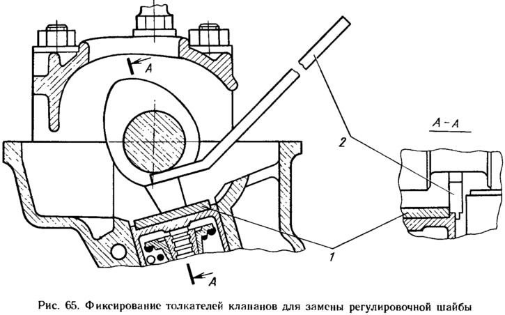
Tool 67.7800.9505 (flat magnet steel plate) or forceps with narrow jaws remove the adjusting washer 1 and measure its thickness with a micrometer. Then determine the thickness of the new washer according to the formula:
where H is the thickness of the new washer; B is the thickness of the removed washer; A - measured gap; C is the nominal gap.
Example. Let's say A \u003d 0.44 mm; B = 3.75 mm; C = 0.35 mm (for exhaust valve). Then W = 3.75 + (0,44—0,35) = 3.84 mm. Within the clearance tolerance of±0.05 mm, we accept the thickness of the new washer equal to 3.85 mm.
A new adjusting washer is installed in the valve tappet, with the marking towards the pusher, the retainer 67.7800.9504 is removed and the gap is checked again. If it is adjusted correctly, then the probe is 0.35 mm thick (for inlet valves 0.2 mm thick) should enter with a slight pinch. Sequentially turning the crankshaft half a turn, which corresponds to turning the mark on the camshaft pulley by 90°, adjust the clearances for the remaining valves, observing the sequence indicated in Table. 6.
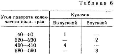
Note. The cam numbers are counted in order from the camshaft pulley.
After adjustment, oil is poured into the oil baths of the cylinder head and the front cover of the toothed belt. Wrap the spark plugs, install the air filter, crankcase ventilation hoses and spare tire.