




When adjusting, make sure that the valve lever is not installed at an angle, as this may result in an overestimation of the actual clearance.
Make adjustments in the following order:
- turn the crankshaft clockwise until the mark on the camshaft sprocket coincides with the mark on the bearing housing, which will correspond to the end of the compression stroke in the fourth cylinder. In this position, the clearance at the exhaust valve of the 4th cylinder is adjusted (8th cam) and the intake valve of the 3rd cylinder (6th cam);
- loosen the lever adjusting bolt nut;
- insert a flat feeler gauge A.95111, 0.15 mm thick, for the intake valve between the lever and the camshaft cam (0.2mm for exhaust valve) and use a wrench to tighten or loosen the bolt, then tighten the lock nut until the feeler gauge enters with a slight pinch when the lock nut is tightened (Fig. 2-42);
- after adjusting the clearance at the exhaust valve of the 4th cylinder and the intake valve of the 3rd cylinder, sequentially turn the crankshaft 180° and adjust the clearances, observing the sequence indicated in Table 2-2.
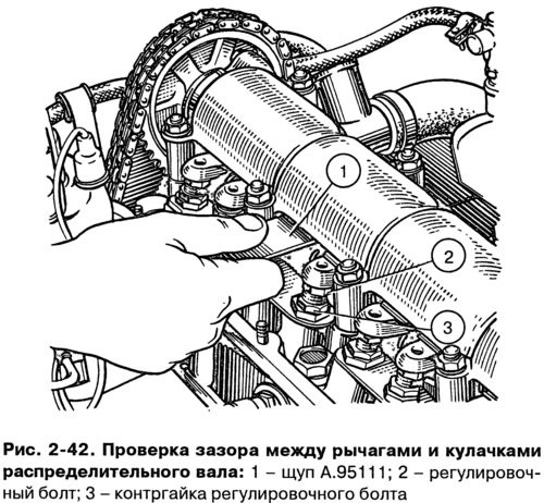
Table 2-2. Valve clearance adjustment sequence
| Crankshaft rotation angle, deg | cylinder number where the compression stroke occurs (end) | no. of adjustable valves (cams) |
| 0 | 4 | 8 and 6 |
| 180 | 2 | 4 and 7 |
| 360 | 1 | 1 and 3 |
| 540 | 3 | 5 and 2 |
(The information is published on the website: «VazBook.ru»)