




Notes:
- The marking of the jets is determined by the flow rate, which is measured using micrometers. The micrometers are adjusted using reference jets.
- The nominal fuel jet consumption is determined by the reference jet using a special method. It is not subject to control during operation.
Carburetor calibration data
Parameter | First camera | Second camera |
| Mixing chamber diameter, mm | 32 | 32 |
| Diffuser diameter, mm | 21 | 23 |
| Main dosing system: fuel jet marking air jet marking | 97,5 | 97,5 |
| Emulsion tube type | 23 | ZC |
| Idle and transition systems: fuel jet marking air jet marking | 42 170 | 50 120 |
| Econostat: nominal fuel jet flow rate | - | 60 |
| Power mode economizer: fuel jet marking spring compression force at a height of 9.5 mm, N | 40 | - |
| Accelerator pump: sprayer marking cam marking fuel supply per 10 cycles, cm³ | 35 7 11,5 | 40 - 11,5 |
| Starting clearances: air damper, mm throttle valve, mm | 3±0,2 0,85 | - - |
| Vacuum corrector hole diameter, mm | 1,2 | - |
| Needle valve hole diameter, mm | 1,8 | |
| Diameter of the fuel bypass hole into the tank, mm | 0,7 | |
| Engine crankcase ventilation hole diameter, mm | 1,5 | - |
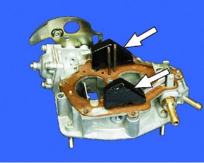
1. The float should rotate freely on the axis without jamming and should not touch the walls of the float chamber. Otherwise, adjust the position of the float as indicated in subsection 11.3.9.
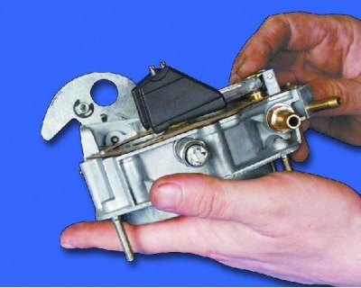
2. The valve needle must move freely in the seat. The tightening torque of the valve seat is 15 N·m (1.5 kgf·m).
[View the original on the internet resource: www.VAZbook.ru]
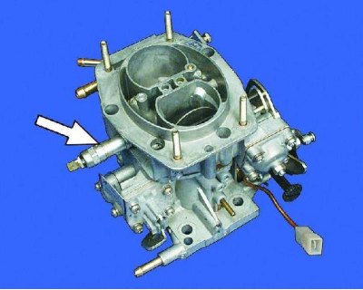
3. The tightening torque of the electromagnetic valve is 4 Nm (0.4 kgf·m).
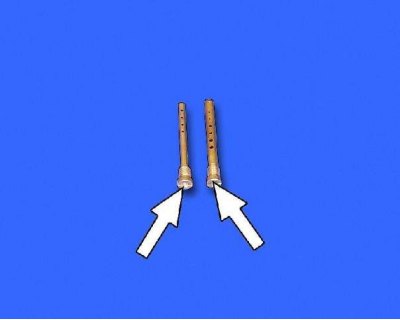
4. Install the jets in accordance with the markings on them (see the table "Carburetor calibration data").
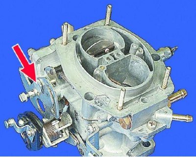
5. If the air damper drive lever was removed, before tightening the lever axle, apply a sealant such as UG-9 to its end and the upper threads.
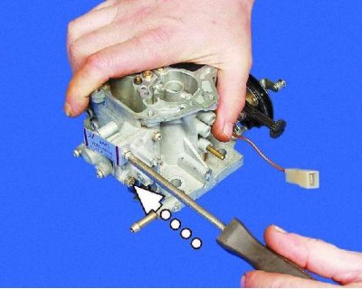
6. When assembling the accelerator pump, tighten the cover mounting screws, press the pump drive lever all the way down and in this position finally tighten the cover mounting screws.
7. Adjust the trigger and check the operation of the second chamber locking mechanism (see subsections 11.3.8. and 11.3.10.).