
In order not to confuse the jets, you need to pay attention to their marking. After assembling the cover 1 of the carburetor, the fuel level in the float chamber is adjusted.
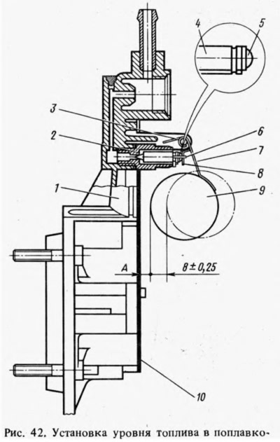
The required level is ensured by the correct installation of serviceable elements of the locking device. The distance between the float and the gasket 10 adjacent to the carburetor cover (size A), should be 7.5 mm±0.25 mm (for carburetors 2105-1107010-20 and 2105-1107010-10 - 6.5 mm±0.25 mm). Size A is adjusted by bending the tongue. The surface of the tongue must be perpendicular to the axis of the valve, not have dents or notches. Dimensional control is carried out with caliber 67.8151.9505. At the same time, hold the cover vertically so that the tongue 8 slightly touches the ball 5 of the needle valve 4 without sinking it. By bending the stop 3 on the bracket 7 adjust the stroke of the float (8±0,25) mm.
When replacing the float or needle valve, check the fuel level setting and replace the seal. When adjusting, make sure that the yoke 6 of the needle valve does not interfere with the free movement of the float. After installing the carburetor cover, check if the float touches the walls of the float chamber. After assembly, carburetor adjustments are made.