




A generator is an electrical machine that converts mechanical energy generated by an engine into electrical energy. When the rotor rotates, alternating current is generated in the three stator windings of the generator, and a rectifier unit with semiconductor diodes is built into the generator to convert it into direct current. The voltage of the current generated by the generator depends on the rotor speed and the excitation current flowing through the rotor winding (excitation winding).
To regulate the current in the excitation winding, an automatic voltage regulator is built into the generator. It maintains a constant voltage in the vehicle's electrical system within 13.2-14.7 V, regardless of the engine crankshaft speed. When powerful consumers of electricity are operating simultaneously and the crankshaft speed is low, (at idle) the voltage in the vehicle's on-board network may be below the specified limit. The battery then stops charging, and if the current consumption is high, it even begins to discharge.
Weak tension of the alternator drive belt causes it to slip on the pulleys, which prevents the alternator from developing the required power and leads to rapid wear of the belt. Indirect belt slippage
the generator can be identified by the dim glow of the headlights at night and by the whistling sound in the front of the engine when the crankshaft speed increases.
Recommendation. If the battery charge indicator light on the instrument panel (dashboard) lights up, do not rush to remove the generator for repair or replacement. First, check the serviceability of fuse F19, the supply of +12V voltage to the generator excitation winding when the ignition is turned on (connector D) and the tension of the generator drive belt. The generator can be checked for serviceability without removing it from the engine.
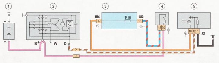
Generator electrical connection diagram: 1 - battery; 2 - generator; 3 - mounting block; 4 - ignition switch; 5 - generator malfunction indicator lamp in the instrument panel
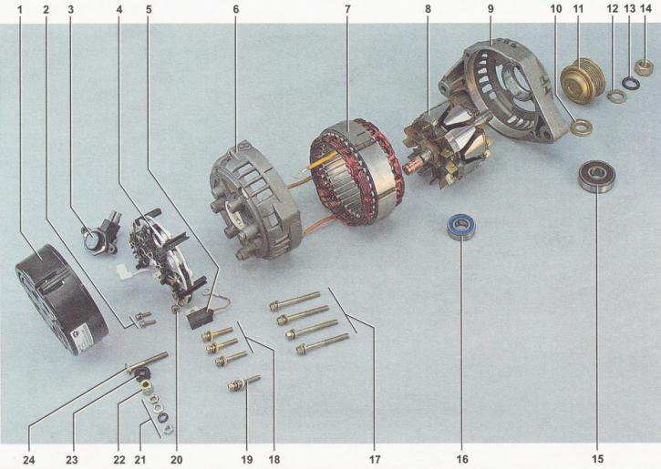
Generator details: 1 - protective cover of the rectifier unit; 2 - voltage regulator mounting screws; 4 - rectifier block; 5 - capacitor; 6 - back cover; 7 - stator with windings; 8 - rotor; 9 - front cover; 10 - spacer sleeve; 11 - pulley; 12 - washer; 13 - spring washer; 14 - pulley mounting nut; 15 - front bearing; 16 - rear bearing; 17 - cover tightening bolts; 18 - bolts (with insulating gaskets) fastenings of the rectifier block and stator winding terminals; 19 - bolt (without insulating lining) rectifier block fastenings; 20 - Capacitor mounting screw; 21 - contact bolt fastening elements; 22 - spacer sleeve; 23 - insulating sleeve; 24 - contact bolt