




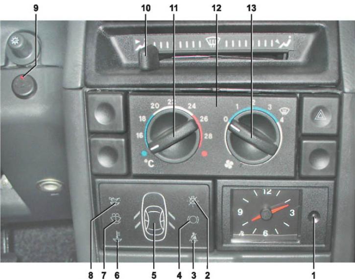
1 - button for adjusting the time on the watch. To set the current time, press the clock button. When pressed once, the clock hands change their position by one minute.
2 - indicator of malfunction of brake light and parking light lamps. After the ignition is turned on, the control system checks the condition of the lamps. If a malfunction is detected, the indicator lights up orange. The indicators only work when the ignition is on. When the ignition is turned on, the indicator unit turns on all the indicators so that the driver can make sure that they are working properly. After self-diagnosis, if no malfunctions are detected, all the indicators of the indicator unit should go out. If a malfunction is detected, it must be eliminated.
3 - seat belt warning light. The indicator lights up red if the driver's seat belt is not fastened. The indicators only work when the ignition is on. When the ignition is on, the indicator unit turns on all the indicators so that the driver can make sure that they are working properly. After self-diagnosis, if no faults are detected, all the indicators of the indicator unit should go out. If a fault is detected, it must be eliminated.
4 - brake pad wear indicator. Installed on some vehicles equipped with brake pads with wear sensors. After the ignition is turned on, the monitoring system monitors the wear of the brake pad linings. When the thickness of the lining of any of the brake pads of the front wheels decreases to 1.5 mm, the indicator lights up orange. The indicators only work when the ignition is on. When the ignition is turned on, the indicator unit turns on all the indicators so that the driver can make sure that they are working properly. After self-diagnosis, if no faults are detected, all the indicators of the indicator unit should go out. If a fault is detected, it must be eliminated.
5 - open door alarm. When the ignition is on, the corresponding symbol lights up red after opening the door. The indicators work only when the ignition is on. When the ignition is on, the indicator unit turns on all the indicators so that the driver can make sure that they are working properly. After self-diagnosis, if no faults are detected, all the indicators of the indicator unit should go out. If a fault is detected, it must be eliminated.
6 - low coolant level indicator in the expansion tank. Lights up orange [The indicators only work when the ignition is on. When the ignition is on, the indicator unit turns on all the indicators so that the driver can check that they are working properly. After self-diagnosis, if no faults are detected, all the indicators of the indicator unit should go out. If a fault is detected, it must be corrected.] when the coolant level drops to the minimum permissible level and the ignition is on.
7 - windshield washer reservoir low fluid level indicator lights up orange if there is less than a liter of windshield washer fluid left in the reservoir. The indicators only work when the ignition is on. When the ignition is turned on, the indicator unit turns on all the indicators so that the driver can make sure that they are working properly. After self-diagnosis, if no faults are detected, all the indicators of the indicator unit should go out. If a fault is detected, it must be fixed.
8 - low oil level indicator in the engine crankcase. Lights up orange if the oil level in the engine crankcase is below the minimum permissible level. When the indicator lights up, check the oil level using the indicator. The indicator unit has a ten-minute delay in the indicator operation after the engine is stopped so that the oil has time to drain into the pan. The indicators only work when the ignition is on. When the ignition is turned on, the indicator unit turns on all the indicators so that the driver can make sure that they are working properly. After self-diagnostics, if no faults are detected, all the indicators in the indicator unit should go out. If a fault is detected, it must be fixed.
9 - LED indicating immobilizer status (see 2.1, pos. 40).
10 - air distributor flap control lever. When the lever is in the extreme left position, the main air flow will be directed to the upper part of the cabin through the central and side ventilation grilles. If the lever is moved to the extreme right position, the main air flow will be directed to the feet of the driver and passengers. When the lever is in the middle position, the main flow will be directed to blowing the windshield. By setting the lever to intermediate positions, you can combine the distribution of air flows in the cabin.
11 - temperature control knob. The regulator can be used to set the desired air temperature in the cabin. For this purpose, on the heater control unit (around the handle) numbers are applied - the temperature in degrees Celsius. An air temperature sensor is installed on the ceiling of the car. When turning the regulator handle in the range indicated by the numbers, the set temperature will be automatically maintained in the cabin. If the handle is turned to the blue sector in the extreme position, unheated air will flow through the heater. When the handle is in the extreme position on the red sector, only heated air will flow into the cabin.
12 - heater control unit. The electronic system automatically maintains the set temperature in the cabin and regulates the speed of the electric fan.
13 - heater fan control handle. The handle has four fixed positions that set the speed of the electric fan ("1" - minimum, "4" - maximum). In the "0" position, the electric fan is off.