
English Русский
Български
Беларускі
Український
Српски
Hrvatski
Română
Polski
Slovenský
Magyar
| Articles | Contacts | Sitemap |   
Repair and maintenance Lada Repair and maintenance Mazda Repair and maintenance Mitsubishi Repair and maintenance Toyota Repair and maintenance Land Rover Repair and maintenance Hyundai Repair and maintenance Nissan
VAZbook.ru


Main     1111   2101   2105   2106   2107   2109   2110   2115   2121  
VAZ-2114 (2004-2013) VAZ-2115 (1997-2012)
  • Main
  • «Samara-2»
  • VAZ-2114
  • Power unit
  • Supply system
  • Fuel module of engine 2111 (1.5i) — removal and installation

Fuel module of engine 2111 (1.5i) — removal and installation (VAZ-2114)

            0

Contents: Removal ↓ Assembly ↓ Installation ↓

Removal


1. Relieve the fuel pressure from the fuel line (see "Fuel line - pressure relief"). After releasing the fuel pressure, do not connect the connecting block to the fuel module.

2. Remove accumulated dust and dirt from the fuel module and treat the threaded connections with penetrating lubricant.

3. With an open-end wrench by 17 mm we unscrew the fuel line fittings.
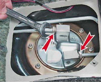
3. With an open-end wrench by 17 mm we unscrew the fuel line fittings.


4. We take the tubes away from the module. There are sealing rubber rings on the ends of the tubes. Damaged rings must be replaced.
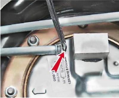
4. We take the tubes away from the module. There are sealing rubber rings on the ends of the tubes.…


5. With a socket wrench by 7 mm we unscrew the eight nuts securing the fuel module.
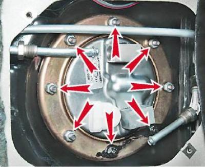
5. With a socket wrench by 7 mm we unscrew the eight nuts securing the fuel module.


6. Remove the fuel module pressure ring.
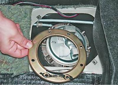


6. Remove the fuel module pressure ring.


7. Carefully remove the fuel module from the tank (at the same time, using a thin slotted screwdriver, we adjust the upper edge of the intake chamber in order to bring it out through the opening of the tank).
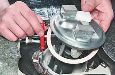
7. Carefully remove the fuel module from the tank (at the same time, using a thin slotted…


Warning! When removing the fuel module, do not bend the fuel level indicator sensor lever. To do this, tilt the module slightly and carefully remove the float from the tank hole.


Note: If it is not possible to remove the fuel module assembly with the intake chamber (a plastic container secured with two rubber bushings to the fuel module cover guides), remove it separately after removing the module.


Assembly


Recommendation: The fuel module must be installed in the tank assembled with the intake chamber.


1. If the module was removed without the intake chamber: use a screwdriver to remove two rubber bushings from the hole in the fuel pump housing lugs.
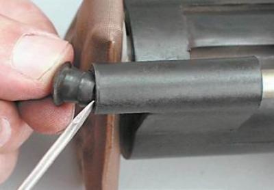
1. If the module was removed without the intake chamber: use a screwdriver to remove two rubber…


Note: One of the bushings may remain in the intake chamber opening.


2. After covering the bushing with a thin layer of motor oil, insert it into the opening of the intake chamber.
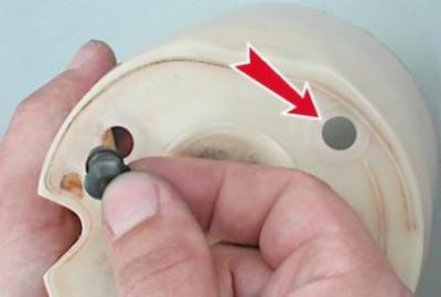
2. After covering the bushing with a thin layer of motor oil, insert it into the opening of the…


3. Place the sealing gasket on the module.

4. Insert the fuel pump into the chamber (the bushings must fit into the holes in the fuel pump housing lugs).
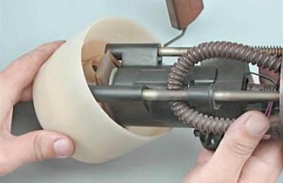
4. Insert the fuel pump into the chamber (the bushings must fit into the holes in the fuel pump…


5. Using a fine punch, insert the bushings into the holes.
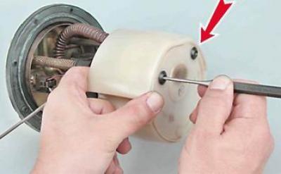
5. Using a fine punch, insert the bushings into the holes.


Installation


1. Carefully insert the float into the tank opening, install the fuel module and orient it in the tank so that the arrow points towards the trunk.
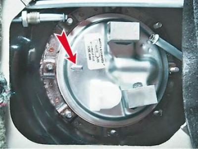
1. Carefully insert the float into the tank opening, install the fuel module and orient it in the…


Warning! When securing the fuel module, make sure the arrow on the fuel module cover points toward the rear of the vehicle. To avoid damaging the studs, do not overtighten the nuts.


2. Install the pressure ring and evenly (in three or four doses) we tighten the nuts securing the module.

3. Connect the fuel line fittings to the fuel module.

4. Turn on the ignition for 5 seconds and check the tightness of the connections. If necessary, tighten the fittings.

5. Install the hatch cover and lower the rear seat cushion.

(Information copied from the portal: VAZbook.ru)


This article is available at russian, bulgarian, belarusian, ukrainian, serbian, croatian, romanian, polish, slovak, hungarian
The text was reviewed by the specialist: Grigory Vologodtsev

Share with friends:

Previous articles
VAZ-2114: Supply system
Next articles

Fuel rail engine 11183 (1.6i) — removal, disassembly and installation
Fuel rail of engine 2111 (1.5i) — removal, disassembly and installation
Fuel rail engine 2111 (1.5i) — replacement of fuel pressure regulator
Fuel filter — replacement
Fuel Line — Pressure Relief
Fuel module engine 2111 (1.5i) — replacement of fuel level indicator sensor
Fuel module of engine 2111 (1.5i) — cleaning of mesh filter
Fuel module engine 2111 (1.5i) — replacement of fuel pump
Fuel module engine 11183 (1.6i) — removal and installation
Fuel module engine 11183 (1.6i) — replacement of fuel level indicator sensor

More articles from other manuals on VAZ cars:
➠ Fuel module of the gasoline pump of the engine 21124 (1.6i) —… VAZ-2110 (1995-2007)
➠ Engine power supply system. Fuel supply, air supply and exhaust… VAZ-2101 (1970-1983)
➠ Starting an engine with a fuel injection system VAZ-2105 (1979-2010)
➠ Engine fuel system parts VAZ-2106 (1976-2006)
➠ Description of the design of the fuel system of a carburetor… VAZ-2107 (1982-2012)
Link in different formats to this page


Visitor comments

No comments yet


How much will 20 + 41 ?


VAZ-2114 (2004-2013) 
  • General information
  • Operation and maintenance
  • Power unit
  • Engine repair
  • Cooling system
  • Supply system
  • Control system
  • Exhaust system
  • Transmission
  • Clutch
  • Car gearbox
  • Front wheel drives
  • Chassis
  • Wheels and tires
  • Front suspension
  • Rear suspension
  • Steering
  • Brake system
  • Body
  • Exterior
  • Interior
  • Doors and glass
  • Tailgate
  • Ventilation and heating
  • Electrical equipment
  • Equipment and devices
  • Headlights and lighting
  • Engine electrics
  • Electrical circuits


VAZ-2115 (1997-2012) 
  • General information
  • Vehicle device
  • Operation manual
  • Vehicle malfunctions
  • Car care
  • Power unit
  • Engine repair
  • Cooling system
  • Supply system
  • Control system
  • Exhaust system
  • Transmission
  • Clutch
  • Car gearbox
  • Front wheel drives
  • Chassis
  • Front suspension
  • Rear suspension
  • Steering
  • Brake system
  • Body
  • Exterior
  • Interior
  • Doors, covers and windows
  • Electrical equipment
  • Equipment and devices
  • Headlights and lighting
  • Engine electrics
  • Anti-theft system


VAZbook.ru © 2017 · Mobile version · Contact with administration · Sitemap: EN BG BY UA RS HR RO PL SK HU · Site search · News and articles VAZ-1111 · VAZ-11113 · VAZ-2101 · VAZ-21011 · VAZ-2104 · VAZ-2105 · VAZ-21051 · VAZ-2106 · VAZ-21061 · VAZ-2107 · VAZ-21099 · VAZ-2109 · VAZ-2108 · VAZ-2110 · VAZ-2112 · VAZ-2114 · VAZ-2115 · VAZ-2121 · VAZ-21213 · VAZ-21214 ·
The site stores technical data using cookies to improve the service.