English Русский
Български
Беларускі
Український
Српски
Hrvatski
Română
Polski
Slovenský
Magyar
| Articles | Contacts | Sitemap |   
Repair and maintenance Lada Repair and maintenance Mazda Repair and maintenance Mitsubishi Repair and maintenance Toyota Repair and maintenance Land Rover Repair and maintenance Hyundai Repair and maintenance Nissan
VAZbook.ru


Main     1111   2101   2105   2106   2107   2109   2110   2115   2121  
VAZ-2121 (1977-1994) VAZ-21213 (1994-2006) VAZ-21214 (1994-2006)
  • Main
  • «Niva»
  • VAZ-21213
  • Power unit
  • Engine repair
  • Removal and installation the engine

Removal and installation the engine (VAZ-21213)

            0

Place the car on a lift or over an inspection pit and apply the parking brake lever. Remove the spare wheel and the spare wheel support tube. Disconnect the wires from the battery and remove it. Loosen the hood hinge bolts and remove the hood.

Remove the air filter, having previously disconnected the hoses from it, having removed the cover and the filter element. Close the carburetor from above with a technological plug.

Disconnect the carburetor throttle actuator rod and the choke control cable from the engine.

Disconnect the wire ends from the solenoid valve and the carburetor limit switch, from the oil pressure and coolant temperature sensors, from the ignition distributor sensor, from the generator and starter.

Drain the coolant from the radiator, cylinder block and heater, for which move the heater tap control lever to the right, unscrew the plugs on the left side of the cylinder block and on the right radiator tank, screw in the drain hose fittings instead and remove the plugs from the expansion tank and radiator.

Remove the fan shroud, first separating its halves. Disconnect the coolant supply and outlet hoses from the engine. Unscrew the two bolts securing the radiator to the body, press up the upper latch of the radiator guide shroud, move the upper part of the radiator toward the engine and remove the radiator from the engine compartment together with the thermostat and hoses. Remove the radiator guide shroud.

Loosen the nuts securing the exhaust pipe to the exhaust manifold. Disconnect the exhaust pipe from the bracket on the gearbox and lower it down.


Loosen the clamps, disconnect the hoses from the fuel pump and secure it in a position that prevents gasoline leakage. Disconnect the fuel drain hose from the carburetor.

Loosen the clamps and disconnect the hoses from the heater pipes, and the brake booster hose from the inlet pipe.

Using the 02.7812.9500 socket wrench, loosen the bolts securing the starter to the clutch housing. Loosen the bolts securing the clutch housing cover to the lower part of the clutch housing. Using the A.55035 socket wrench, loosen the bolts securing the clutch housing to the cylinder block.

Hang the TCO-3/379 crossbar on the hoist and secure the engine on the right side by the bracket installed on the front exhaust manifold mounting stud, and on the left side by the clutch housing mounting hole.

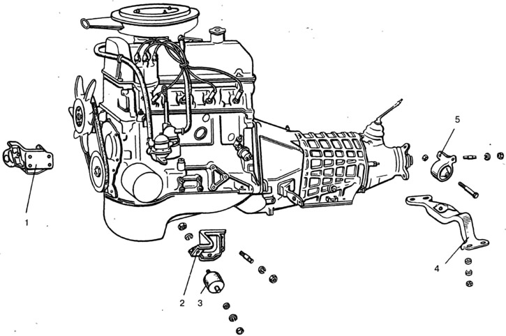
Slightly tighten the hoist chain, unscrew the nuts securing the cushions 3 (Fig. 2-3) of the front engine mount to the side brackets, unscrew the nuts and bolt securing the front axle housing to the engine brackets. Disconnect the ground wire from the engine.

Fig. 2-3. Engine mount:

Fig. 2-3. Engine mount:
1 - right engine mount bracket with cushion; 2 - left engine mount bracket; 3 - pillow; 4 - rear engine mount cross member; 5 - bracket with support for the rear engine mount.


Remove the engine by first lifting it up to clear the suspension mount bolts from the bracket holes, then moving it forward to clear the end of the transmission input shaft from the bearing located in the crankshaft flange.

Remove the starter heat shield, starter and hot air intake together with the supply hose. Remove the two side brackets with the front engine mount cushions from the cylinder block.

Loosen the clutch mounting bolts and remove it.

Install the engine on the vehicle in the reverse order of removal. Pay special attention to connecting the engine to the gearbox: the drive shaft must fit precisely into the splines of the clutch driven disk.

In addition, to ensure centering of the engine and transfer case, it is necessary that the centering washers of the front engine mount cushions enter the corresponding holes in the side brackets.


This article is available at russian, bulgarian, belarusian, ukrainian, serbian, croatian, romanian, polish, slovak, hungarian
The text was reviewed by the specialist: Grigory Vologodtsev

Share with friends:

Previous articles
VAZ-21213: Engine repair
Next articles

Possible engine malfunctions, their causes and methods of elimination
Cross and longitudinal sections of the engine
Disassembling the engine
Engine assembly
Engine running-in after repair
Checking the engine on a car after repair
Features of the cylinder block device

More articles from other manuals on VAZ cars:
➠ The structure of a car engine VAZ-1111 (1988-1996)
➠ General structure of a car engine VAZ-2101 (1970-1983)
➠ The engine structure of VAZ-2104 and VAZ-2105 cars VAZ-2105 (1979-2010)
➠ The engine structure of VAZ-2106 and VAZ-2103 cars VAZ-2106 (1976-2006)
➠ Engine hood VAZ-2107 (1982-2012)
Link in different formats to this page


Visitor comments

No comments yet


How much will 46 + 27 ?


VAZ-2121 (1977-1994) 
  • General information
  • Vehicle device
  • Car VAZ-21219
  • Power unit
  • Engine repair
  • Cooling system
  • Lubrication system
  • Supply system
  • Transmission
  • Clutch
  • Car gearbox
  • Transfer case
  • Cardan gear
  • Rear axle and gearbox
  • Front axle
  • Chassis
  • Front suspension
  • Rear suspension
  • Steering
  • Brake system
  • Body
  • Exterior
  • Interior
  • Doors and windows
  • Electrical equipment
  • Equipment and devices
  • Headlights and lighting
  • Engine electrics


VAZ-21213 (1994-2006) 
  • General information
  • Vehicle device
  • User manual
  • Power unit
  • Engine repair
  • Cooling and lubrication system
  • Supply system
  • Transmission
  • Clutch
  • Car gearbox
  • Transfer case
  • Cardan gear
  • Rear axle and shafts
  • Front axle and wheel drive
  • Chassis
  • Wheel suspension
  • Steering
  • Brake system
  • Body
  • Exterior
  • Interior
  • Electrical equipment
  • Engine electrics
  • Equipment and devices


VAZ-21214 (1994-2006) 
  • General information
  • Vehicle information
  • Troubleshooting
  • Power unit
  • Engine repair
  • Cooling system
  • Fuel system (carburetor)
  • Fuel system (injector)
  • Ignition system
  • Control system
  • Exhaust system
  • Transmission
  • Clutch
  • Car gearbox
  • Transfer case
  • Cardan gear
  • Front axle
  • Rear axle
  • Chassis
  • Front suspension
  • Rear suspension
  • Steering
  • Brake system
  • Body
  • Exterior
  • Interior
  • Doors, covers and windows
  • Ventilation and heating
  • Electrical equipment
  • Equipment and devices
  • Headlights and lighting
  • Engine electrics
  • Electrical circuits


VAZbook.ru © 2017 · Mobile version · Contact with administration · Sitemap: EN BG BY UA RS HR RO PL SK HU · Site search · News and articles VAZ-1111 · VAZ-11113 · VAZ-2101 · VAZ-21011 · VAZ-2104 · VAZ-2105 · VAZ-21051 · VAZ-2106 · VAZ-21061 · VAZ-2107 · VAZ-21099 · VAZ-2109 · VAZ-2108 · VAZ-2110 · VAZ-2112 · VAZ-2114 · VAZ-2115 · VAZ-2121 · VAZ-21213 · VAZ-21214 ·
The site stores technical data using cookies to improve the service.