




Open large image in new tab »
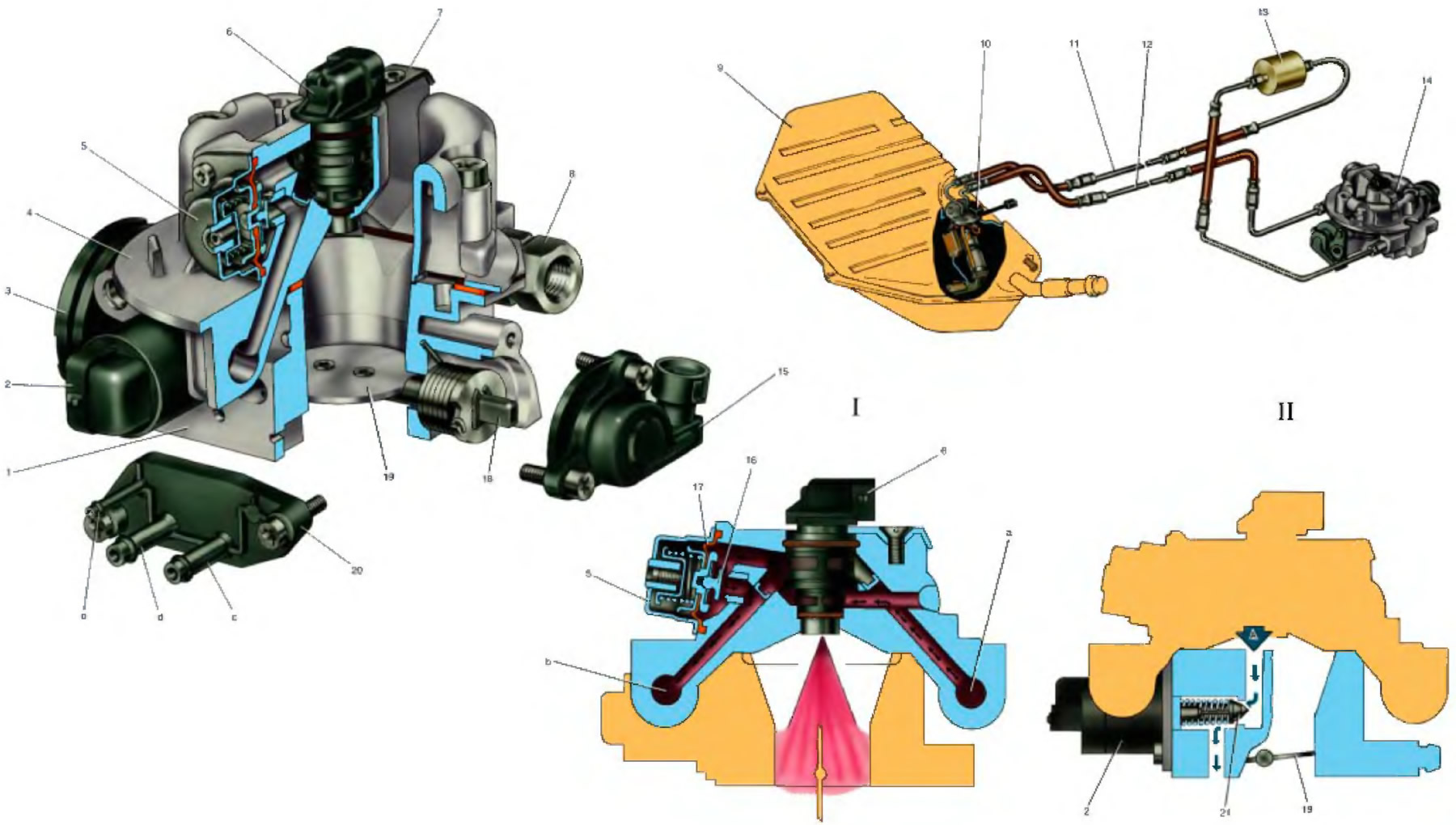
1. Throttle body of the central fuel injection unit; 2. Idle speed control; 3. Throttle actuator sector; 4. Fuel supply housing of the central fuel injection unit; 5. Fuel pressure regulator; 6. Nozzle; 7. Nozzle holder; 8. Fuel supply nipple; 9. Fuel tank; 10. Electric fuel pump with fuel level sensor; 11. Fuel supply line; 12. Fuel drain line; 13. Fuel filter; 14. Central fuel injection unit; 15. Throttle position sensor; 16. Fuel pressure regulator valve; 17. Diaphragm; 18. Throttle shaft; 19. Throttle valve; 20. Vacuum tube module; 21. Idle speed control valve.
a. Fuel supply channel; b. Fuel drain channel; p. Pipe for purge hose of adsorber; d. Crankcase ventilation hose connection; e. Hose connection to the absolute pressure sensor.
I. Fuel pressure regulator operation diagram; II. Idle speed control circuit diagram: A - air supply bypassing the throttle valve.
a. Fuel supply channel; b. Fuel drain channel; p. Pipe for purge hose of adsorber; d. Crankcase ventilation hose connection; e. Hose connection to the absolute pressure sensor.
I. Fuel pressure regulator operation diagram; II. Idle speed control circuit diagram: A - air supply bypassing the throttle valve.
[View the original on the internet resource: VAZBOOK]