
English Русский
Български
Беларускі
Український
Српски
Hrvatski
Română
Polski
Slovenský
Magyar
| Articles | Contacts | Sitemap |   
Repair and maintenance Lada Repair and maintenance Mazda Repair and maintenance Mitsubishi Repair and maintenance Toyota Repair and maintenance Land Rover Repair and maintenance Hyundai Repair and maintenance Nissan
VAZbook.ru


Main     1111   2101   2105   2106   2107   2109   2110   2115   2121  
VAZ-2121 (1977-1994) VAZ-21213 (1994-2006) VAZ-21214 (1994-2006)
  • Main
  • «Niva»
  • VAZ-21213
  • General information
  • Vehicle device
  • Brake operation diagram

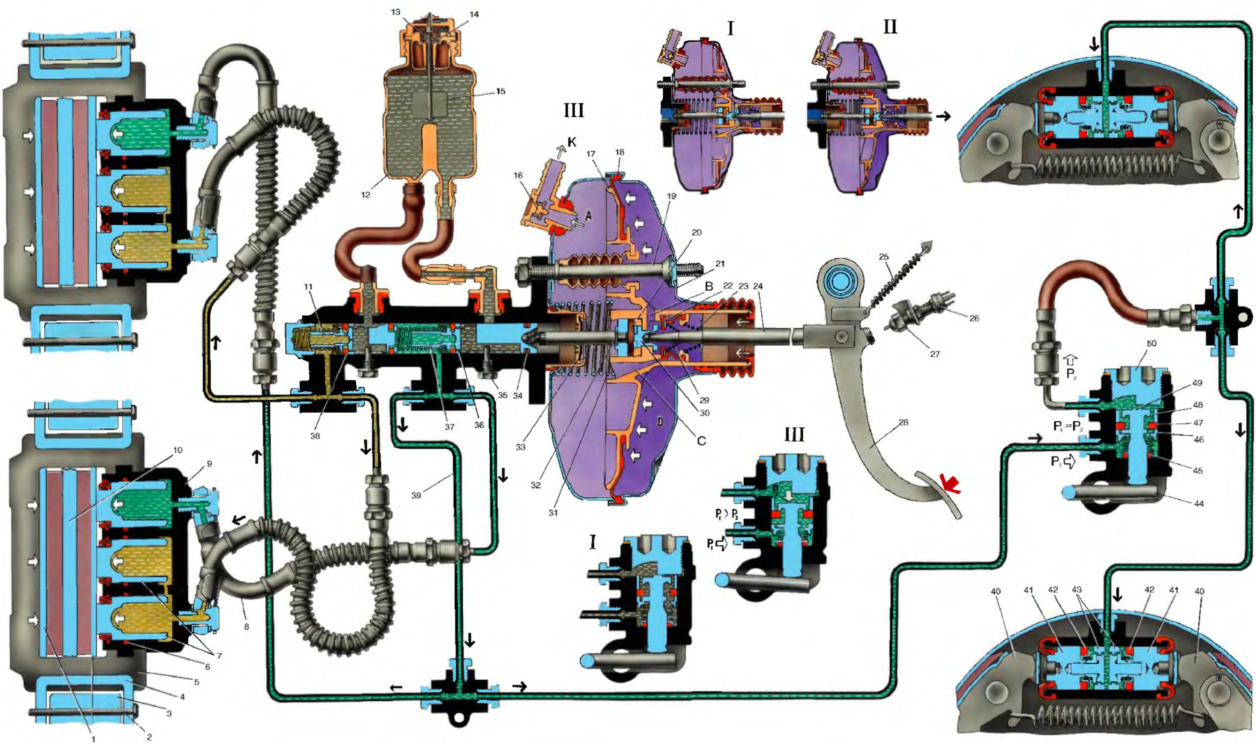
Brake operation diagram (VAZ-21213)

            0

Open large image in new tab »
1. Brake pads; 2. Clamping lever axis; 3. Shoe guide; 4. Caliper pressure lever; 5. Brake caliper; 6. Piston sealing ring; 7. Primary circuit wheel cylinder pistons; 8. Secondary circuit brake hose; 9. Cylinder block; 10. Brake disc; 11. Primary circuit drive piston of the master cylinder; 12. Brake hydraulic fluid reservoir; 13. Movable contact; 14. Fixed contact; 15. Float; 16. Vacuum valve; 17. Vacuum booster valve body; 18. Diaphragm; 19. Amplifier pin; 20. Rod buffer; 21. Amplifier housing cover; 22. Vacuum booster valve; 23. Valve return spring; 24. Valve tappet; 25. Pedal release spring; 26. Brake light switch; 27. Brake light switch tip; 28. Brake pedal; 29. Valve spring; 30. Piston; 31. Valve body return spring; 32. Rod; 33. Rod seal; 34. Sealing ring; 35. Piston stroke limiting screw; 36. Bushing; 37. Secondary circuit drive piston; 38. Seal; 39. Secondary circuit pipeline; 40. Brake pads; 41. Rear brake wheel cylinder piston; 42. Piston seal; 43. Thrust rings; 44. Pressure regulator drive lever; 45. Sealing ring; 46. Spring plate; 47. Piston head seal; 48. Housing bushing; 49. Pressure regulator piston; 50. Pressure regulator housing plug.

A. Vacuum cavity; B. Channel connecting the atmospheric cavity with the internal cavity of the valve body; C. Channel connecting the internal cavity of the valve body with the vacuum cavity; K. To the engine intake pipe; D. Atmospheric cavity.

I. The pedal is not pressed; II. Disinhibition; III. Braking.


The information is published on the website: vazbook.ru


This article is available at russian, bulgarian, belarusian, ukrainian, serbian, croatian, romanian, polish, slovak, hungarian
The text was reviewed by the specialist: Grigory Vologodtsev

Share with friends:

Previous articles
VAZ-21213: Vehicle device
Next articles

Wheel brake mechanisms
Steering system
Shock absorber device
Rear suspension device
Front suspension device
Electrical diagram of the VAZ-21213 car
Generator device (carburetor engine)
Generator device 94.3701 (injection engine)
Starter device
Ignition system device

More articles from other manuals on VAZ cars:
➠ Brake operation diagram VAZ-2101 (1970-1983)
➠ Brake operation diagram VAZ-2109 (1984-1997)
➠ Gearbox operation diagram VAZ-1111 (1988-1996)
➠ Operation diagram of a five-speed gearbox VAZ-2105 (1979-2010)
➠ Four-speed gearbox operation diagram VAZ-2106 (1976-2006)
Link in different formats to this page


Visitor comments

No comments yet


How much will 15 + 22 ?


VAZ-2121 (1977-1994) 
  • General information
  • Vehicle device
  • Car VAZ-21219
  • Power unit
  • Engine repair
  • Cooling system
  • Lubrication system
  • Supply system
  • Transmission
  • Clutch
  • Car gearbox
  • Transfer case
  • Cardan gear
  • Rear axle and gearbox
  • Front axle
  • Chassis
  • Front suspension
  • Rear suspension
  • Steering
  • Brake system
  • Body
  • Exterior
  • Interior
  • Doors and windows
  • Electrical equipment
  • Equipment and devices
  • Headlights and lighting
  • Engine electrics


VAZ-21213 (1994-2006) 
  • General information
  • Vehicle device
  • User manual
  • Power unit
  • Engine repair
  • Cooling and lubrication system
  • Supply system
  • Transmission
  • Clutch
  • Car gearbox
  • Transfer case
  • Cardan gear
  • Rear axle and shafts
  • Front axle and wheel drive
  • Chassis
  • Wheel suspension
  • Steering
  • Brake system
  • Body
  • Exterior
  • Interior
  • Electrical equipment
  • Engine electrics
  • Equipment and devices


VAZ-21214 (1994-2006) 
  • General information
  • Vehicle information
  • Troubleshooting
  • Power unit
  • Engine repair
  • Cooling system
  • Fuel system (carburetor)
  • Fuel system (injector)
  • Ignition system
  • Control system
  • Exhaust system
  • Transmission
  • Clutch
  • Car gearbox
  • Transfer case
  • Cardan gear
  • Front axle
  • Rear axle
  • Chassis
  • Front suspension
  • Rear suspension
  • Steering
  • Brake system
  • Body
  • Exterior
  • Interior
  • Doors, covers and windows
  • Ventilation and heating
  • Electrical equipment
  • Equipment and devices
  • Headlights and lighting
  • Engine electrics
  • Electrical circuits


VAZbook.ru © 2017 · Mobile version · Contact with administration · Sitemap: EN BG BY UA RS HR RO PL SK HU · Site search · News and articles VAZ-1111 · VAZ-11113 · VAZ-2101 · VAZ-21011 · VAZ-2104 · VAZ-2105 · VAZ-21051 · VAZ-2106 · VAZ-21061 · VAZ-2107 · VAZ-21099 · VAZ-2109 · VAZ-2108 · VAZ-2110 · VAZ-2112 · VAZ-2114 · VAZ-2115 · VAZ-2121 · VAZ-21213 · VAZ-21214 ·
The site stores technical data using cookies to improve the service.